SSRD-240D40 Tyco Electronics, SSRD-240D40 Datasheet - Page 2
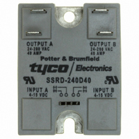
SSRD-240D40
Manufacturer Part Number
SSRD-240D40
Description
SSR, PANEL MOUNT, 280VAC, 15VDC, 40A
Manufacturer
Tyco Electronics
Series
SSRDr
Datasheet
1.SSRD-240D25R.pdf
(2 pages)
Specifications of SSRD-240D40
Control Voltage Range
4VDC To 15VDC
Operating Voltage Range
24Vrms To 280Vrms
Load Current
40A
Isolation Voltage
4000Vrms
Control Voltage Type
DC
Relay Terminals
Screw
Circuit
DPST (2 Form A)
Output Type
AC, Zero Cross
Voltage - Input
4 ~ 15VDC
Voltage - Load
24 ~ 280 V
Mounting Type
Chassis Mount
Termination Style
Quick Connect - .250" (6.3mm)
Package / Case
Hockey Puck
Load Voltage Rating
280 V
Load Current Rating
0.1 A to 40 A
Contact Form
1 Form A (SPST-NO)
Output Device
SCR
Relay Type
Solid State
Mounting Style
Chassis
Turn-on Switching
Zero
Lead Free Status / RoHS Status
Lead free / RoHS Compliant
On-state Resistance
-
Lead Free Status / Rohs Status
Lead free / RoHS Compliant
Other names
1-1393030-6
PB550
PB550


Operating Diagram
Electrical Characteristics (Thermal Derating Curves)
*See Derating Curves
† Random Turn-on Units have a Random Turn-on circuit instead of Zero Voltage Circuit
Outline Dimensions
Dimensions are shown for
reference purposes only.
Output Specifications (@ 25° C, unless otherwise specified)
VDC Input
Control B
VDC Input
Control A
Parameter
Load Voltage Range V
Peak Voltage (Min.)
Load Current Range I *
Thermal Resistance, Junction to Baseplate (R
Turn-On Time (Max.)
Turn-Off Time (Max.)
I t Rating
Load Power Factor Rating
One Second Surge Current (Max.)
Single Cycle Surge Current (Max.)
Leakage Current (Off-State) (Max.)
On-State Voltage Drop (Max.)
Static dv/dt (Off-State) (Min.)
2
50.0
40.0
30.0
20.0
10.0
0.0
25A Units
+
+
–
–
20
25
30
Ambient Temperature ( C)
35
L
L
40
45
VOLTAGE
VOLTAGE
50
CIRCUIT
CIRCUIT
Tolerance: .035 (0.88)
ZERO
ZERO
55
60
†
†
65
70
J-B
Dimensions are in inches over
(millimeters) unless otherwise
specified.
75
) (Max.)
80
0.7 C/W
1.0 C/W
1.5 C/W
2.0 C/W
A2
B2
A1
B1
(32.0)
Output A
Output B
1.26
(22.6)
.89
Both Sections On
f = 47 - 63 Hz.
V = 280V rms
Issued 3-03 (PDF Rev. 9-04)
Conditions
L
Resistive
t = 1 Min.
t = 8.3 ms
I = Max.
I = Max.
f = 60 Hz.
f = 60 Hz.
L
L
Catalog 1308242
Specifications and availability
subject to change.
Heatsink Recommendations
• We recommend that solid state relay modules be mounted to a
• The heatsink mounting surface should be a smooth (30-40 micro-inch
• An even coating of thermal compound (Dow Corning DC340 or
• The module should be mounted to the heatsink using two #10 screws.
heatsink sufficient to maintain the module’s base temperature at less
than 85°C under worst case ambient temperature and load conditions.
finish), flat (30-40 micro-inch flatness across mating area), un-painted
surface which is clean and free of oxidation.
equivalent) should be applied to both the heatsink and module mounting
surfaces and spread to a uniform depth of .002” to eliminate all air
pockets.
80.0
70.0
60.0
50.0
40.0
30.0
20.0
10.0
0.0
40A Units
20
mA rms
A Sec.
A peak
A peak
V peak
V peak
A rms
25
Units
V rms
V/ s
2
C/W
ms
ms
30
Ambient Temperature ( C)
35
40
Input Terminal Connectors are available from
several different manufacturers.
AMP P/N: 103976-3 or 640440-4
Methode P/N: 1300-004-422
Consult your local distributor for these or
equivalent connectors.
45
50
<0.1 for Random Voltage Turn-On Models
55
8.33 for Zero Voltage Turn-On Models
25A Models
60
0.1-25
1,041
150
500
1.4
0.6
65
70
75
0.5 - 1.0
24-280
8.33
500
80
550
0.1
0.5 C/W
1.0 C/W
1.5 C/W
2.0 C/W
www.tycoelectronics.com
Technical support:
Refer to inside back cover.
40A Models
0.1-40
2,435
234
780
1.3
0.6
P&B
1107
Related parts for SSRD-240D40
Image
Part Number
Description
Manufacturer
Datasheet
Request
R

Part Number:
Description:
SSRD-240D25R=SSA/SSR
Manufacturer:
Tyco Electronics
Datasheet:

Part Number:
Description:
RELAY SSRD DL 40A 240VAC AC OUT
Manufacturer:
Tyco Electronics
Datasheet:

Part Number:
Description:
RELAY DUAL SSR 32VDC QC.250
Manufacturer:
Tyco Electronics
Datasheet:

Part Number:
Description:
SSR, PANEL MOUNT, 280VAC, 15VDC, 25A
Manufacturer:
Tyco Electronics
Datasheet:

Part Number:
Description:
SSRD-240DE40=RELAY,SLSOPC,QC.250/SQ.025,
Manufacturer:
TE Connectivity
Part Number:
Description:
Battery Interconnection System for Portable Electronics; BU CONN FS6 8POS DIP TYPE ASSY ( AMP )
Manufacturer:
Tyco Electronics
Part Number:
Description:
Manufacturer:
Tyco Electronics
Datasheet:
Part Number:
Description:
Manufacturer:
Tyco Electronics
Datasheet: