G3VM-61B1 Omron, G3VM-61B1 Datasheet
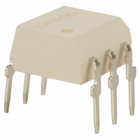
SSR, MOSFET, 60V, 500mA

G3VM-61B1

Manufacturer Part Number
G3VM-61B1
Description
SSR, MOSFET, 60V, 500mA
Manufacturer
Omron
Series
G3VMr
Datasheets

Specifications of G3VM-61B1

Load Voltage Max
60VAC
Load Current
500mA
On State Resistance Max
2ohm
Contact Configuration
SPST-NO
Isolation Voltage
2500Vrms
Forward Current If
7.5mA
Relay Terminals
Through Hole
Height
3.65mm
Circuit
SPST-NO (1 Form A)
Output Type
AC, DC
On-state Resistance
2 Ohm
Voltage - Input
1.15VDC
Voltage - Load
0 ~ 60 V
Mounting Type
Through Hole
Termination Style
PC Pin
Package / Case
6-DIP (0.300", 7.62mm)
Control Voltage Range
1 V to 1.3 V
Load Voltage Rating
60 V
Off State Leakage Current (max)
1 uA
Load Current Rating
500 mA
Contact Form
1 Form A
Output Device
MOSFET
Mounting Style
PCB
Relay Type
MOSFET Relay
Turn-on Switching
FET
Current, Rating
500 mA
Function
Analog-Switching
Number Of Pins
6
Standards
UL, RoHS
Termination
Solder
Voltage, Rating
60 VAC
Rohs Compliant
Yes
Depth
6.4mm
Lead Free Status / RoHS Status
Lead free / RoHS Compliant
Lead Free Status / RoHS Status
Lead free / RoHS Compliant, Lead free / RoHS Compliant
Other names
G3VM61B1
Z2102

Available stocks

Company
Part Number
Manufacturer
Quantity
Price
Part Number:
G3VM-61B1
Manufacturer:
OMRON
Quantity:
12 000
Analog-switching MOS FET Relays for
High Switching Currents, with Dielectric
Strength of 2.5 kVAC between I/O.
• Upgraded G3VM-61 B/E Series.
• Switches minute analog signals.
• Leakage current of 1 µA max. when output relay is open.
RoHS compliant
.!
■ Application Examples
• Measurement devices
• Security systems
• Amusement machines
■ List of Models
■ Dimensions
Note:
■ Terminal Arrangement/Internal Connections (Top View)
■ PCB Dimensions (Bottom View)
12
G3VM-61B1
G3VM-61B1
Note: The actual product
G3VM-61B1
SPST-NO
Contact form
MOS FET Relays
is marked different-
ly from the image
shown here.
All units are in millimeters unless otherwise indicated.
PCB terminals
Surface-mounting
terminals
2.54
(1.52)
Terminals
3.65
+0.15
−0.25
2.5 min.
6.4±
2.54
6
1
0.8±
0.25
0.25
Six 0.8-dia. holes
7.12±
5
2
(1.52)
(0.61)
(0.61)
0.5±
60 VAC
0.25
Load voltage (peak value)
2.54±
1.2±
0.1
4
3
0.25
0.15
7.85 to 8.80
7.62±
Weight: 0.38 g
0.25
0.25
+0.1
−0.05
G3VM-61E1
G3VM-61E1
Note: The actual product
G3VM-61B1
G3VM-61E1
G3VM-61E1(TR)
Note:
■ Actual Mounting Pad Dimensions
G3VM-61E1
(Recommended Value, Top View)
Model
is marked different-
ly from the image
shown here.
The actual product is marked differently from the image
shown here.
50
---
8.3 to 8.8
Number per stick
3.65
6.4±
6
1
1.3
+0.15
−0.25
2.54
0.25
2.54±
1.5
7.12±
5
2
0.25
0.25
1.2±
G3VM-61B1/E1
2.54
0.15
4
3
---
1,500
1.0
min.
Number per tape
Weight: 0.38 g
10.0 max.
7.62±
0.25
1.0 min.
4.0
+0.25
−0.2

Related parts for G3VM-61B1

G3VM-61B1 Summary of contents

Page 1

... Weight: 0.38 g G3VM-61E1 4 3 ■ Actual Mounting Pad Dimensions (Recommended Value, Top View) G3VM-61E1 G3VM-61B1/E1 Number per stick Number per tape 50 --- --- 1,500 7.12± 0.25 6.4± 0.25 7.62± 0.25 +0 ...

Page 2

... Safety Precautions Refer to “Common Precautions” for all G3VM models. G3VM-61B1/E1 1. The dielectric strength between the input and output was checked by applying voltage be- tween all pins as a group on the LED side and all pins as a group on the light-receiving side. ...

Page 3

... Terminal 3 is connected to the internal circuit. Do not connect anything to terminal 3 externally. Pin Strength for Automatic Mounting Load In order to maintain the characteristics of the relay, the force imposed on any pin of the relay for automatic mounting must not exceed the following. In direction A: 1. direction B: 1.96 N G3VM Series ...

Page 4

... Do not throw or drop components. If the laminated packag- ing material is damaged, airtightness will be lost. 6. Tape cut SSOPs are packaged without humidity resistance. Use manual soldering to mount them. G3VM Series Soldering 230 to 260 ° max. 245 to 260 ° max. ...

Related keywords