RJCSR1A60D30EPNO CARLO GAVAZZI, RJCSR1A60D30EPNO Datasheet - Page 4
RJCSR1A60D30EPNO
Manufacturer Part Number
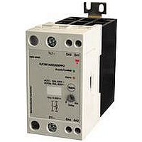
RJCSR1A60D30EPNO
Description
SSR, DIN RAIL MOUNT, 660VAC, 32VDC, 30A
Manufacturer
CARLO GAVAZZI
Datasheet
1.RJCSR1A23D30EPPO.pdf
(7 pages)
Specifications of RJCSR1A60D30EPNO
Control Voltage Type
DC
Control Voltage Range
4VDC To 32VDC
Operating Voltage Range
42VAC To 660VAC
Peak Surge Current
600A
Contact Configuration
SPST
Load Current
30A


4
Alarm Operation
1.1 Current Setpoint
The current setpoint is the
nominal operating current that
is expected when all the heater
loads are functioning properly.
If the heater loads are faulty or
the supply voltage is not close
to the nominal level, the wrong
setpoint will be stored.
1.2 Initialisation
When the device is shipped,
no setpoint is stored in the
flash memory. Both green
and red LEDs will flash inter-
mittently to indicate that a
setpoint must be stored
using the TEACH procedure.
The load will not go on when
the control is applied so long
as a TEACH command is
succesful.
1.3 Local Functions
Local functions can be acti-
vated by using the push
button on the front of the
device. While an alarm is
being issued by any SSR
connected to the common
alarm line or a remote com-
mand is being issued, no
local commands are accept-
ed.
1.3.1 Local TEACH
Press and hold the push but-
ton for approximately 3 sec-
onds. The red LED will flash
after each second. After the
LED flashes 3 times, release
the button. If the “teach” com-
mand has been accepted the
heater loads are automatically
switched ON. The red LED will
flash quickly 10 times. When
the current setpoint has been
stored successfully, the red
and green LEDs will scroll inter-
mittently to indicate that the
TEACH procedure has been
completed. The load will now
be switched on or off accord-
ing to the control input’s status
It is very important to hold
the button down for only 3
flashes of the red LED to
make a successful TEACH.
If the TEACH procedure is
not successful, the device
will automatically reset to
factory default (i.e. no set-
point stored).
1.3.2 Local RESET
When an alarm has occurred
the device can be locally
RESET by pressing the push
button for 1 second. The red
LED will flash once. This will
reset the alarm. If the alarm
condition has been cleared
RJCS
the device will return to nor-
mal operation. If the alarm
condition is still active, the
device will automatically go
back to alarm status.
1.3.3 Local TEST
In the absence of a signal on
the “control input” terminal, a
local TEST can be made by
pressing and holding the but-
ton for 5 seconds. After the red
LED flashes 5 times, release
the button. The device will
switch ON the loads for 1 sec-
ond. This test detects if there is
an under-current or heater
break alarm condition.
1.4 Remote Setup
Procedure
Remote functions can be
activated with a PLC or any
other logic controller by
applying timed pulses to the
alarm terminal: >10V for
RJCS...PO and <10V for
RJCS...NO.
1.4.1 Remote TEACH
Apply a 3 second pulse. The
red LED will flash after each
second. After the LED flash-
es 3 times and the “teach”
command has been accept-
ed, the heater loads (of all
SSRs connected to the
same alarm line) are auto-
matically switched ON and
the red LED will flash quickly
10 times. When the current
setpoint has been stored
successfully, the red and
green LEDs will scroll inter-
mittently to indicate that the
TEACH procedure has been
completed. The load will now
be switched on or off accord-
ing to the control input’s status
1.4.2
UNBLOCK
When an alarm has occurred
the device can be remotely
RESET by applying a 1 sec-
ond pulse. A 1 second pulse
will
TEACH of all SSRs connect-
ed to the similar alarm line.
The red LED will flash once.
This will reset the alarm. If
the alarm condition has been
cleared the device will return
to
RJCS only, if the alarm con-
dition is still active, the
device will automatically go
back to alarm status.
1.4.3 Remote BLOCK
Applying a 5 second pulse
will induce the device to
normal
also
Remote
unblock
operation.
RESET/
local
In
block local TEACH. After
this, no local TEACH com-
mands are accepted. To
unblock
remote
issued. In the case of the
RJCS, if 24V supply is
removed,
BLOCK is
REMOTE BLOCK should be
issued.
2 Alarms
2.1 Alarm DELAY
A potentiometer on the front
of the device allows a time
delay on the heater break
alarm between 2s and 40s
for
between 0 and 40s for the
RJCSR1A...
For heaters having a low
cold resistance, the time for
the inrush current to decay
to a value less than 13% of
the current set-pint, must be
added to the potentiometer
alarm delay setting plus a
further 20ms.
For an alarm signal to occur,
the alarm condition must
persist throughout this time
period. The alarm output is
enabled only after this time
delay has passed. However,
if the control input is dis-
abled for a period of time
equal to four times the delay
setting, the internal alarm
delay timer is reset automat-
ically. (see example)
2.2 Relay remains OFF due
to Line Voltage Loss or
Thyristor
Failure. (85ms for RJCSR
and 500ms for RJCS)
The device generates one
pulse with duration of 7 sec-
onds on the alarm terminal.
This alarm is non-latching.
The red LED remains ON
after this alarm condition
until a RESET is issued.
2.3 Heater Break.
A Heater Break alarm is
given if the current mea-
sured through the device is
13% less than the current
setpoint stored in the flash
memory for a period of time
greater or equal to the alarm
delay potentiometersetting.
The device generates one
pulse with duration of 8 sec-
onds on the alarm terminal.
The alarm signal is non-
latching.
remains ON after this alarm
condition until a RESET is
made. If the measured cur-
Specifications are subject to change without notice (05.07.2007)
the
RESET
this
RJCS1A...
The
Open
local
lost.
situation,
red
must
Another
Circuit
TEACH
LED
and
be
a
rent changes to within 10%
of the Current Setpoint,
before the Alarm DELAY
time has elapsed, the Alarm
DELAY timer is reset.
2.4 Over-temperature or
Over-current.
This alarm occurs if any one
of following two conditions
is true:
1. The device detects an
internal
condition at any time during
operation and switches off
the output. The red LED
flashes intermittently.
2. A current above the nomi-
nal device rating is mea-
sured during current set-
point TEACH. This action
erases the current setpoint
from flash memory and both
red and green LEDs will flash
intermittently until a TEACH
procedure with an accept-
able current is carried out.
In both cases, the device
generates one pulse with
duration of 9 seconds on the
alarm terminal. The alarm
signal is non-latching.
2.5 Thyristor Short Circuit.
(110ms for RJCSR and 90ms
for RJCS)
The device generates one
pulse with duration of 10
seconds on the alarm termi-
nal. The alarm signal is non-
latching.
The red LED remains ON
after this alarm condition
until a RESET is made.
2.6 Alarms Connected in
Parallel to one PLC Input
and one PLC Output.
For REMOTE operation, up
to 50 devices can be con-
nected in parallel to at least
one PLC input. This PLC
input must also be connect-
ed in parallel to the PLC out-
put. The PLC input must be
programmed
alarms while the PLC output
must be programmed to
supply the pulses required
for REMOTE Setup. When
more than one device is pre-
sent, pulses from the PLC
output or alarm pulses from
any device will cause the red
LEDs on all devices in paral-
lel to flash intermittently for a
max. of 6.25 seconds. After
this time, it is only devices
with an alarm condition that
will have their red LED on.
over-temperature
to
detect
Related parts for RJCSR1A60D30EPNO
Image
Part Number
Description
Manufacturer
Datasheet
Request
R

Part Number:
Description:
MAGNETIC CYLINDRICAL PROX. SENSOR
Manufacturer:
CARLO GAVAZZI
Datasheet:
Part Number:
Description:
CYLINDRICAL MAGNETIC SENSOR
Manufacturer:
CARLO GAVAZZI
Datasheet:
Part Number:
Description:
MAGNETIC CYLINDRICAL PROX. SENSOR
Manufacturer:
CARLO GAVAZZI
Datasheet:
Part Number:
Description:
Current and Voltage Controls / Current Transformer / 3-Phase
Manufacturer:
Carlo Gavazzi
Datasheet:

Part Number:
Description:
Definite Purpose Contactor
Manufacturer:
CARLO GAVAZZI
Datasheet:
Part Number:
Description:
Definite Purpose Contactor
Manufacturer:
CARLO GAVAZZI
Datasheet: