8952110000 Weidmuller, 8952110000 Datasheet - Page 99
8952110000
Manufacturer Part Number
8952110000
Description
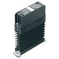
SSR, DIN RAIL MOUNT, 275VAC, 32VDC, 20A
Manufacturer
Weidmuller
Datasheet
1.8952110000.pdf
(142 pages)
Specifications of 8952110000
Control Voltage Type
DC
Control Voltage Range
3VDC To 32VDC
Operating Voltage Range
12VAC To 275VAC
Peak Surge Current
250A
Load Current
20A
Switching Mode
Zero Cross
Rohs Compliant
No


Technical data
Ordering data
Accessories
Mini-coupler DKO
• Coupling of digital
• Inexpensive solution for adapting
• Low input power
• Screw connection system
• 6 mm width
• For mounting on TS 35
Control side
Rated voltage
Power rating
max. input frequency
Nominal auxiliary voltage
Status indicator
Load side
Nominal switching voltage
Nominal switching current
Voltage drop at max. load
Switch-on delay/Switch-off delay
Short-circuit-proof/Protective circuit
General data
Ambient temperature (operational)
Storage temperature
Approvals
Insulation coordination (EN 50 178)
Standards
Rated voltage
Rated impulse withstand voltage
Clearance and creepage distances for
control side - load side
Surge category
Pollution severity
Dimensions
Clamping range (rating- / min. / max.) mm
Length x width x height
Note
Connection system
Note
Note
sensor/actuator signals between
PLC and process
level and potential
A / 195 mW
mn;20 %
Screw connection
mm
2
24 V DC 200 Hz
Control side
24 V DC ±10%
max. 145 mW
200 Hz
no
LED green
Load side
5…48 Vdc
500 mA
≤ 800 mV
approx. 40 μs/approx. 65 μs
no/diode
General data
-25 °C…+40 °C
-40 °C…+85 °C
CE;
Insulation coordination (EN 50 178)
EN 50178
300 V
4.0 kV
≥ 4 mm
side - load side
III
2
Screw connection
4 / 0.5 / 4
65 x 6 x 57
Type
DKO 35 24VDC E:O
Input at top
End plate
AP DKT4
2
ollution severity
ge category
minal auxiliary voltage
Input
1
24 V=
0 V
rovals
impulse withstand voltage
voltage
nput frequency
l switching current
and creepage distances for control
rcuit-proof/Protective circuit
0687560000
drop at max. load
s
dicator
itching voltage
VA / 195 mW
%
ture (operational)
ture
(Qty.=1)
delay
Order No.
8215630000
Output
48 V=
0,5 A
+
3
4
24 V DC 50 kHz
Control side
24 V DC ±20 %
max. 112 mW
50 kHz
no
LED green
Load side
5 VTTL
8 mA, fan out = 20 LS-TTL
1 μs/2.5 μs
no/diode
General data
-25 °C…+40 °C
-25 °C…+85 °C
CE;
Insulation coordination (EN 50 178)
EN 50178
300 V
4.0 kV
≥ 5.5 mm
side - load side
III
2
Screw connection
4 / 0.5 / 4
77 x 6 x 62
Type
DKO DK5 24VDC 50KHZ
Input at top
End plate
AP DK 5 PA BE: 4036780000
4
5
Voltage drop at max. load
GND
ollution severity
ge category
minal auxiliary voltage
Output
rovals
TTL
impulse withstand voltage
voltage
nput frequency
l switching voltage
3
rcuit-proof/Protective circuit
nd creepage distances for control
s
dicator
elay/Switch-off delay
+ 5V
V C
C
VA / 195 mW
ture (operational)
ture
(Qty.=1)
Input
Order No.
8228640000
+ 24V
0 V
1
2
24 V UC
Control side
24 V DC ±20 %
max.: 220 mVA / 195 mW
≤ 10 Hz
no
LED *
Load side
24 V DC ±20%
2 A
2 ms/7 ms
yes/
General data
-25 °C…+50 °C
-40 °C…+85 °C
CE;
Insulation coordination (EN 50 178)
EN 50178
300 V
6.0 kV
≥ 5.5 mm
side - load side
III
2
Screw connection
4 / 0.5 / 4
77 x 6 x 62
* Status indicator: green = OK, yellow = partial short
circuit, blinking red = short circuit
Type
DKO DK5 24VUC
Input at bottom
End plate
AP DK 5 PA BE: 4036780000
5
Voltage drop at max. load
GND
ollution severity
ge category
minal auxiliary voltage
inal switching current
rovals
t-circuit-proof/Protective circuit
s indicator
impulse withstand voltage
4
voltage
Output
frequency
nd creepage distances for control
s
delay/Switch-off delay
Optos - DK-SERIES
3
+ 24V
oltage
V C
ture (operational)
ture
C
(Qty.=1)
+ 24V
Input
Order No.
8228630000
1
C.99
0 V
2
C
Related parts for 8952110000
Image
Part Number
Description
Manufacturer
Datasheet
Request
R


Part Number:
Description:
STANDARD I.C. PIN
Manufacturer:
Mill-Max Manufacturing Corp.

Part Number:
Description:
MK 3/6
Manufacturer:
Weidmuller
Datasheet:
Part Number:
Description:
SL 5.08/7/90 3.2SN OR Omnimate Range 5.08
Manufacturer:
Weidmuller
Datasheet:
Part Number:
Description:
SL 5.08/18/90 3.2SN OR Omnimate Range 5.00/5.08
Manufacturer:
Weidmuller
Part Number:
Description:
SL 5.08/24/90 3.2SN OR Omnimate Range 5.00/5.08
Manufacturer:
Weidmuller