RE8RA21FU TELEMECANIQUE, RE8RA21FU Datasheet
RE8RA21FU
Specifications of RE8RA21FU


Related parts for RE8RA21FU


RE8RA21FU Summary of contents
Page 1
Applications 2 Enclosure type Timing range Number of ranges Extreme values Output circuit Control circuit voltage, depending on model Type Pages Te 2/2 Electronic timers Selection guide Electronic timers enable simple automation cycles to be set up using wired logic. ...
Page 2
Relay outputs provide complete isolation between the supply circuit and the output possible to have several output circuits. Universal: multi-voltage, multifunction timing ranges 7 0.05…1 s 0.15…3 s 0.5…10 s 1.5…30 s 5…100 s 15…300 ...
Page 3
... The On and Off delays are adjusted by 2 different potentiometers. Energisation of the relay causes the output contact to close instantaneously and start the timing period. The contact returns to its initial position when the set time delay (t) has elapsed or if the supply is cut off before the end of the timing period. ...
Page 4
... External control of starting: opening of an external contact connected to the relay starts the timing period. Closing of this contact resets the timer. External control of partial stop of time delay: closing of an external contact connected to the relay allows the timing period to be interrupted. The time elapsed is memorised ...
Page 5
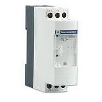
... Zelio Time - timing relays Relay output, width 22.5 mm, optimum General characteristics The RE8 range of relays is designed for simple and repetitive applications, providing basic functions. Each relay comprises single timing range C/O output relay. These products have a transparent, hinged flap on their front face to prevent any accidental alteration of the settings. ...
Page 6
... Relay output, width 22.5 mm, optimum References : General characteristics pages 2/38 and 2/40 Dimensions : page 2/42 Schemes, setting-up : pages 2/39, 2/41 and 2/43 Time delay characteristics Setting accuracy the full scale value Repeat accuracy Influence of voltage In the voltage range, 0.9…1.1 Un Influence of temperature Immunity to ...
Page 7
... 110…240 V (1) For easier adjustment preferable to set the time delay between the maximum value in the range and one tenth of this value. Example: RE8-TA11BUTQ timing range 0.1 s…10 s, recommended use 1 s…10 s. (2) Also available in pack of one; delete TQ from the end of the reference. Example: RE8-TA11BU. ...
Page 8
... Start – 1 Potentiometer for fine adjustment of the time delay, graduated range max. setting 2. 2 Marking of maximum time delay value. 3 LEDs, depending on the models : - Yellow LED: illuminates when the output relay is energised, - Green LED: illuminates when the RE8 is energised. Adjustment of the time delay - The maximum value of the timing range is printed on the product, 2. Example: RE8-TA61BUTQ ...
Page 9
... V 10 (1) For easier adjustment preferable to set the time delay between the maximum value in the range and one tenth of this value. Example: RE8-PE11BUTQ timing range 0.1 s…10 s, recommended use 1 s…10 s. (2) Correct operation of the star-delta starter is only possible if the wiring scheme on page 2/41 is strictly complied with. ...
Page 10
... KM3 – K1T (1) Y (1) K1T: RE8-YGi1iiTQ 1 Potentiometer for fine adjustment of the time delay, graduated range max. setting 2. 2 Marking of maximum time delay value. 3 LEDs, depending on the models : - Yellow LED: illuminates when the output relay is energised, - Green LED: illuminates when the RE8 is energised. ...
Page 11
... Characteristics : pages 2/36 and 2/37 References : pages 2/38 and 2/40 Schemes, setting-up : pages 2/39, 2/41 and 2/43 RE8 Dimensions 2 80 Rail mounting 89,5 82 Screw fixing Te 2/42 Zelio Time - timing relays Relay output, width 22.5 mm, optimum Dimensions, mounting 22,5 Ø 4 ...
Page 12
... Zelio Time - timing relays Relay output, width 22.5 mm, optimum Characteristics : pages 2/36 and 2/37 References : Schemes pages 2/38 and 2/40 Dimensions : page 2/42 Setting-up : pages 2/39 and 2/41 Control of several relays with a single external control contact RE8-RA The external control contact C may be an electronic control device, for example a 2-wire sensor. In this case A1- and the control device can only control maximum of 4 relays ...