QM4HS-U2C-240V PANASONIC EW, QM4HS-U2C-240V Datasheet - Page 3
QM4HS-U2C-240V
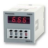
Manufacturer Part Number
QM4HS-U2C-240V
Description
TIMER, DELAYED, 8 PINS, 240VAC
Manufacturer
PANASONIC EW
Datasheet
1.QM4HS-U2C-240V.pdf
(3 pages)
Specifications of QM4HS-U2C-240V
Contact Configuration
DPDT
Nom Input Voltage
240V
Delay Time Range
0.01s To 9990h
Adjustment Type
Pushbutton
Relay Mounting
Panel
Svhc
No SVHC (15-Dec-2010)
External Depth
72mm
External Length /
RoHS Compliant


QM4H
DIMENSIONS
Panel cut-out dimensions
OPERATION MODE
• QM4H-S Type
1) T.D. mode
2) INST. mode
PRECAUTIONS IN USING THE QM4H
1. Avoid locations subject to flammable
or corrosive gases, excessive dust, oil,
vibrations, or excessive shocks.
2. Since the main-unit is made of
polycarbonate resin, avoid contact with or
use in environments containing methyl
alcohol, benzene, thinners, and other
organic solvents; and ammonia, caustic
sodas, and other alkaline substances.
3. Power supply superimposed surge
protector
Although a surge protector will withstand
standard-waveform voltage with the
values in the next table, anything above
this will destroy the internal circuit. You
46
• S Type
1.772
1.772
Dimensions A when n products
are installed continuously:
A = (48∗n–2.5
Power supply
Time delay contact
(N.O. contact)
1-3 or 6-8
OP.LED
Power supply
Time delay contact
(N.O. contact) 6-8
Instantaneous contact
(N.O. contact) 1-3
OP.LED
TIMER
T.D.
45
45
MODE
8
-
+
+0.6
+.024
+0.6
+.024
0
0
0
0
INST.
8
-
+
1.772
8 S
-
+
45
QM4H-S
+0.6
+0.6
+.024
-
+
0
0
0
)
A
A = (1.890∗n–.098
ON
• G Type
ON
ON
TIMER
8
-
+
T
T
-
8
+
1.890
48
8
+.024
-
+
0
QM4H-G
S
-
+
)
ON
ON
.374
Panel Mounting Diagram
9.5
.236
6
should therefore use a surge absorber.
• Surge waveform
[±(1.2×50) µs uni-polar full wave voltage]
4. In order to maintain the characteristics,
do not remove the timer case.
5. When installing the panel, use the
supplied AQM4812 main-unit
mounting frame. Note that the AT8-DA4
is also available for sale separately.
6. If you change the operating voltage,
be sure not to allow leak current into
the timer.
12 to 48 V AC/DC
Panel (Thickness: 1 to 5 mm .039 to
OFF
OFF
OFF
OFF
OFF
1,000 V
Mounting screw
(supplied with mounting frame)
Mounting frame (AQM4812: supplied)
(AT8-DA4 can also be used for
mounting frame. Sold separately)
2.854
72.5
(3.362)
• QM4H-G Type
* Set the reset inputs 1 to 3 and stop inputs 1 to 4 to 20 ms or higher.
* When shorting a signal, please set the inter-terminal resistance to 1 kΩ or less,
(85.4)
and the inter-terminal residual voltage to 2 V or less.
When releasing, please set the inter-terminal resistance to 100 kΩ or greater.
Power supply
Reset 1-3
Stop 1-4
Time delay contact
(N.O. contact) 6-8
OP.LED
07/2004
Lit
100 to 240 V AC/DC
.197
6,000 V
12.9
.508
inch)
Blinking
ON
ta
44.5
1.752
T: Setting time
ON
T
Notes:
1. Operating voltage signs in parentheses ( ) indicate the polarity
2.
7. Avoid leaving the unit powered
continuously. Leaving the unit
powered up with output set to ON
continuously for a long period of time
(about 1 month or more) will wear out
the electronic components. If you will
be keeping it powered continuously,
combine with a relay to create the
circuit shown below:
T.D.
of the DC type.
ON
Blinking slowly
ON
MODE
t1+t2 = T
is a time delay contact.
is an instantaneous contact.
Terminal layouts and Wiring diagrams
t1
INST.
ON
MODE
R
RESET
R
ta<T
t2
• QM4H-S Type
• QM4H-G Type
NO
STOP
COM
COM
ON
NC
TD mode: Time delay 2C
INST mode:
Time delay 1C and
Instantaneous 1C
*Use MODE switch on front
Operating
3
2
3
2
Operating
voltage
T
voltage
4
1
4
1
5
8
5
8
Tolerance: ±1.0
6
7
6
7
NC
NC
COM
COM
T
NO
NO
(units: mm inch)
R
.039
Related parts for QM4HS-U2C-240V
Image
Part Number
Description
Manufacturer
Datasheet
Request
R

Part Number:
Description:
TIMER, DELAYED, 8 PINS, 12-48VDC
Manufacturer:
PANASONIC EW
Datasheet:

Part Number:
Description:
POWER RELAY, 24VDC, 30A, SPST-NO
Manufacturer:
PANASONIC EW
Datasheet:

Part Number:
Description:
POWER RELAY, SPDT, 12VDC, 10A, PC BOARD
Manufacturer:
PANASONIC EW

Part Number:
Description:
POWER RELAY, 24VDC, 5A, SPST-NO, PCB
Manufacturer:
PANASONIC EW
Datasheet:


Part Number:
Description:
SIGNAL RELAY, DPDT, 4.5VDC, 1A, SMD
Manufacturer:
PANASONIC EW
Datasheet:

Part Number:
Description:
SIGNAL RELAY, DPDT, 4.5VDC, 1A, THD
Manufacturer:
PANASONIC EW
Datasheet:

Part Number:
Description:
MINIATURE RELAY, DPDT, 24VDC, 2A, THD
Manufacturer:
PANASONIC EW


Part Number:
Description:
SIGNAL RELAY, DPDT, 5VDC, 2A, PC BOARD
Manufacturer:
PANASONIC EW
Datasheet:
Part Number:
Description:
SIGNAL RELAY, DPDT, 5VDC, 2A, PC BOARD
Manufacturer:
PANASONIC EW
Datasheet:


Part Number:
Description:
PHOTOMOS RELAY, 60VDC, 400mA
Manufacturer:
PANASONIC EW
Datasheet:

Part Number:
Description:
PHOTOMOS RELAY, 400V, 150mA
Manufacturer:
PANASONIC EW
Datasheet: