H3DE-S2 Omron, H3DE-S2 Datasheet - Page 12
H3DE-S2
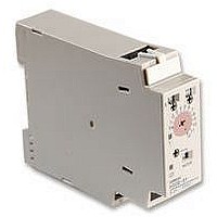
Manufacturer Part Number
H3DE-S2
Description
TIMER, MULTIFUNCTION
Manufacturer
Omron
Datasheet
1.H3DE-S2.pdf
(14 pages)
Specifications of H3DE-S2
Contact Configuration
DPCO
Nom Input Voltage
230V
Delay Time Range
0.1s To 120h
Adjustment Type
Screwdriver Slot
Relay Mounting
DIN Rail
Svhc
No SVHC (15-Dec-2010)
Coil Voltage Vac Nom
230V


H3DE
Switching Current vs. Ambient Temperature
(When Mounting Two or More H3DE Units Side-by-Side)
Relationship between Input and Power Supply
Circuits
Since the input circuit and the power supply circuit are configured
independently, the input circuit can be turned on or off irrespective of
the on/off state of the power supply.
It must be noted that a voltage equivalent to the power supply volt-
age is applied to the input circuit.
When connecting a relay or a transistor as an external signal input
device, pay attention to the following points to prevent short-circuit-
ing due to a sneak current to the transformerless power supply.
If a relay or transistor is connected to two or more Timers, the input
terminals of those Timers must be wired properly so that they will not
be different in phase or the terminals will be short-circuited to one
another (refer to the figures below).
34
(Measurement Condition: Input voltage of 230 VAC)
Input/Output
70
60
50
40
30
20
0
AC/DC
power
supply
1
2
Input circuit
3
B1
4
A2
Power supply
circuit
5
Mounting
clearance: 5 mm
Mounting clearance:
50 mm min.
Mounting
clearance: 10 mm
Mounting
clearance: 0 mm
A1
Load current (A)
Maximum range of
operating ambient
temperature
The H3DE Series is provided with a transformerless power supply
system.
The input wires must be as short as possible. If the floating capacity
of wires exceeds 2,000 pF (approx. 17 m for cables with 120 pF/m),
the operation will be affected. Pay particular attention when using
shielded cables.
The H3DE has a high impedance circuit. Therefore, the H3DE may
not be reset if the H3DE is influenced by inductive voltage. In order
to eliminate any influence of inductive voltage, the wires connected
to the H3DE must be as short as possible and should not be
installed alongside power lines. If the H3DE is influenced by induc-
tive voltage that is 30% or more of the rated voltage, connect a CR
filter with a capacitance of approximately 0.1 F and a resistance of
approximately 120
ply terminals. If there is any residual voltage due to current leakage,
connect a bleeder resistor between the power supply terminals.
Incorrect
Correct
Input Wires
Wiring (H3DE-H)
Contact or transistor for
external input signal
Contact or transistor for
external input signal
Short-circuit
current
Short-circuit
current
or a bleeder resistor between the power sup-
B1
B1
B1
B1
H3DE
H3DE
H3DE
H3DE
A1
A2
A1
A2
A1
A2
A1
A2
Power supply
Power supply
H3DE
Related parts for H3DE-S2
Image
Part Number
Description
Manufacturer
Datasheet
Request
R

Part Number:
Description:
RELAY TIMER ANALOG DIN 4 MODE
Manufacturer:
Omron
Datasheet:

Part Number:
Description:
RELAY TIMER ANALOG DIN 8 MODE
Manufacturer:
Omron
Datasheet:

Part Number:
Description:
RELAY TIMER ANALOG DIN 4 MODE
Manufacturer:
Omron
Datasheet:

Part Number:
Description:
RELAY TIMER ANALOG DIN 8 MODE
Manufacturer:
Omron
Datasheet:

Part Number:
Description:
TIMER STAR-DELTA 22.5MM DIN MNT
Manufacturer:
Omron
Datasheet:

Part Number:
Description:
TIMER 22.5MM 1-120S DIN MNT
Manufacturer:
Omron
Datasheet:
Part Number:
Description:
TIMER 22.5MM .1-12S DIN MNT
Manufacturer:
Omron
Datasheet:
Part Number:
Description:
TIMER 22.5MM .1-12S DIN MNT
Manufacturer:
Omron
Datasheet:
Part Number:
Description:
TIMER 22.5MM 1-120S DIN MNT
Manufacturer:
Omron
Datasheet:

Part Number:
Description:
TIMER DIN MNT 22.5mm
Manufacturer:
Omron
Datasheet:

Part Number:
Description:
G6S-2GLow Signal Relay
Manufacturer:
Omron Corporation
Datasheet:
Part Number:
Description:
Compact, Low-cost, SSR Switching 5 to 20 A
Manufacturer:
Omron Corporation
Datasheet:
Part Number:
Description:
Manufacturer:
Omron Corporation
Datasheet: