389FXCXC1M-12D Magnecraft / Schneider Electric, 389FXCXC1M-12D Datasheet
389FXCXC1M-12D
Specifications of 389FXCXC1M-12D


Related parts for 389FXCXC1M-12D


389FXCXC1M-12D Summary of contents
Page 1
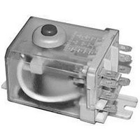
... Power Relays/One, Two or Three Pole 20-30 Amp Rating (DC and AC) Oversized current carrying parts to run cooler and last longer Full range of contact ratings to meet a wide variety of applications A variety of covers and mounting options Contact Viewing Window UL Recognized WHITE File No. E43641 General Specifications - (UL 508) ...
Page 2
... Part Number 7200 Ω 389FXBXC1M-240A 1700 Ω 389FXBXC1M-120A 4600 Ω 389FXCXC1M-240A 1200 Ω 389FXCXC1M-120A 100 Ω 389FXBXC1M-12D 400 Ω 389FXBXC1M-24D 100 Ω 389FXCXC1M-12D 400 Ω 389FXCXC1M-24D 1100 Ω 389FHXXC1-120A 4300 Ω 389FHXXC1-240A 44 Ω 389FXHXC1-24A 1100 Ω 389FXHXC1-120A 100 Ω 389FHXXC1-12D 400 Ω ...
Page 3
... Power Relays/One, Two or Three Pole 20-30 Amp Rating (DC and AC) continued Push Button Indicator Flag UL Recognized WHITE File No. E43641 SPDT-NC-NO-(DB-DM) 6/14 NEW! Available Indicator Lamp Side Flange Cover WIRING DIAGRAMS BOTTOM VIEW WIRING DIAGRAMS VIEWED FROM PIN END SPDT DPDT ...
Page 4
P.C. TERMINALS 0.046 TYP. (1.16) 0.026 (0.66) 0.206 TYP. (5.23) PUSH BUTTON 0.156 0.28 MAX 1.9 MAX (3.96) (7.1) 0.288 (48.42) (7.31) TOP FLANGE COVER STYLE TOP FLANGE COVER STYLE Option C3 1.9 MAX (48.42) SIDE FLANGE COVER STYLE 0.06 ...