LY4 24 VDC Omron, LY4 24 VDC Datasheet
LY4 24 VDC
Specifications of LY4 24 VDC


Related parts for LY4 24 VDC


LY4 24 VDC Summary of contents
Page 1
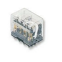
General-purpose Relay MK-I/-S Exceptionally Reliable General-purpose Relay Features Mechanical Indicator/Push Button • Breaks relatively large load currents despite small size. • Long life (minimum 100,000 electrical operations) assured by silver contacts. • Built-in operation indicator (Mechanical, LED), push button, diode ...
Page 2
Ordering Information ■ List of Models Type Terminal Contact form Standard Plug-in DPDT 3PDT LED Indicator DPDT (see note 2) 3PDT Diode DPDT (see note 2) 3PDT Varistor DPDT 3PDT VDE approved DPDT 3PDT LED Indicator DPDT VDE approved 3PDT ...
Page 3
... General-purpose Relay Max. voltage Power consumption 90% to110% of Approx. 2.3 VA (at rated voltage 60 Hz) Approx. 2.7 VA (at 50 Hz) Approx. 1.5 W Max. voltage Power consumption 90% to110% of Approx. 2.0 VA (at rated voltage 60 Hz) Approx. 2.4 VA (at 50 Hz) Approx. 1.3 W MK-I/-S A-47 ...
Page 4
... Rated load 250 VAC 10A at 28 VDC Rated carry current 10 A Max. switching voltage 250 VAC, 250 VDC Max. switching current 10 A Max. switching power 2,500 VA, 280 W ■ Characteristics Contact resistance Operate time Release time Max. operating frequency Insulation resistance Dielectric strength ...
Page 5
Approved Standards The following ratings apply to all models. UL 508 (File No. E41515)/CSA 22.2 No.0/14 (File No. LR35535) Coil ratings 6 to 110 VDC VDC (resistive 240 VAC 10 A, 250 VAC (resistive) ...
Page 6
... Switching current (A) A-50 General-purpose Relay Maximum Switching Power 100 MK-I/-S AC resistive load DC resistive load 28 VDC max inductive load 100 300 500 700 ...
Page 7
... Dimensions Note: All units are in millimeters unless otherwise indicated. ■ Relays 0.8 52.5 max. 34.5 max. 34.5 max. Sockets See below for Socket dimensions. Socket Surface-mounting Socket (for track or screw mounting) Finger-protection models Maximum carry current 2 poles PF083A-E PF083A 3 poles PF113A-E PF113A Note: Use the Surface-mounting Sockets (i.e., finger-protection models) with “ ...
Page 8
Hold-down Clips PFC-A1 Mounting Tracks PFP-100N, PFP-50N (Conforming to EN 50022) 4 1000 (500)* * This dimension applies to the PFP-50N Mounting Track. Mounting Height with Sockets Surface-mounting Sockets 87.8 Two 77.8 ...
Page 9
Terminal Arrangement/Internal Connection (Bottom View) Standard MK2P-I, -S (AC/DC Coil VDE-approved Type MK2P-I-VD, -S-VD MK2P2-I-VD, -S-VD MK3P-I-VD, -S-VD MK3P2-I-VD, -S-VD MK3P5-I-VD, -S-VD (AC/DC Coil Dual Numbering (12) (22 (14) 3 ...
Page 10
LED Indicator Type MK2PN-I, -S (DC Coil: Standard Polarity (+) LED Indicator Type MK2PN1-I, -S (DC Coil: Reverse Polarity Diode Type MK2PD-I, -S (DC Coil: Standard Polarity ...
Page 11
LED Indicator and MK2PND-I, -S Diode Type (DC Coil (+) ( ) LED Indicator and MK2PNV-I, -S Varistor Type (AC Coil VDE Approved Type MK2PN-I-VD, -3-VD LED Indicator ...
Page 12
VDE Approved Type MK2PD1-I-VD, -S-VD Diode Type (12) (DC Coil: 4 Reverse Polarity) (14 (A1) 1 (11) (21 VDE Approved Type MK2PN-I-VD, -S-VD LED Indicator Type (12) (AC Coil) 4 (14 (A1) 1 (11) ...