G7J-4A-B 24DC Omron, G7J-4A-B 24DC Datasheet - Page 8
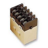
G7J-4A-B 24DC
Manufacturer Part Number
G7J-4A-B 24DC
Description
RELAY, 4PNO, 24VDC
Manufacturer
Omron
Datasheet
1.G7J-2A2B-B_24DC.pdf
(9 pages)
Specifications of G7J-4A-B 24DC
Relay Type
Power
Coil Voltage Vdc Nom
24V
Contact Current Max
25A
Contact Voltage Ac Nom
220V
Contact Voltage Dc Nom
30V
Coil Resistance
288ohm
Coil Type
DC Coil
Coil Current
83mA
Nom Operating Power
2W
Contact Configuration
4PNO
Rohs Compliant
Yes
Lead Free Status / RoHS Status
Lead free / RoHS Compliant


G7J
Precautions
Refer to page NO TAG for general precautions.
Installation
PCB Terminal-equipped Relays weigh approximately 140 g. Be
sure that the PCB is strong enough to support them. We recom-
mend dual-side through-hole PCBs to reduce solder cracking from
heat stress.
Mount the G7J with its test button facing downwards. The Relay
may malfunction due to shock if the test button faces upwards. Be
careful not to press the test button by mistake because the contacts
will go ON if the test button is pressed.
Be sure to use the test button for test purposes only.
The test button is used for Relay circuit tests, such as a circuit conti-
nuity test. Do not attempt to switch the load with the test button.
Minute Loads
The G7J is used for switching power loads, such as motor, trans-
former, solenoid, lamp, and heater loads. Do not use the G7J for
switching minute loads, such as signals. Use a Relay with a bifur-
cated contact construction for switching minute loads, in which
case, however, only SPST-NO or SPST-NC output is obtained.
Soldering PCB Terminals
Be sure to solder the PCB terminals manually only. In the case of
automatic soldering, some flux may stick to the test button and the
G7J. As a result, the G7J may malfunction.
The G7J is not of enclosed construction. Therefore, do not wash the
G7J with water or any detergent.
8
Terminal Arrangement/Internal Connections
G7J-4A-P(B) (T) (Z)
Accessories (Order Separately)
R99-04 W-bracket (for G5F)
14
24
34
44
A2
13
23
33
43
A1
G7J-3A1B-P(B) (T) (Z)
The coil has no polarity.
14
24
34
42
A2
30
35
44
13
23
33
41
A1
Two, M4 or 4.5 dia.
4.4
24
9
29
G7J-2A2B-P(B) (T)
28
14
24
32
42
A2
Connecting
Refer to the following diagram when connecting a wire with a screw
terminal to the G7J.
Allow suitable slack on leads when wiring, and do not subject the
terminals to excessive force.
Tightening torque: 0.98 N S m
Do not impose excessive external force on the G7J in the horizontal
or vertical directions when inserting the G7J to the Faston recep-
tacle or pulling the G7J out from the Faston receptacle. Do not at-
tempt to insert or pull out more than one G7J Unit together.
Do not solder the tab terminals.
Note: Numbers in parentheses are for air feed use.
#250
terminal
(6.35 mm
in width)
Terminal
7
A1
13
23
31
41
AMP170333-1
(170327-1)
AMP170334-1
(170328-1)
AMP170335-1
(170329-1)
4.5
Note: Terminals 43 and 44 of the
7
Receptacle
G7J-4A-P(B)(T)(Z) and contacts 41
and 42 of the G7J-3A1B-P(B)(T)(Z)
are bifurcated contacts.
7.6
Mounting Holes
M3.5
35$0.1
AMP172076-1: natural
AMP172076-4: yellow
AMP172076-5: green
AMP172076-6: blue
Two, M4
8.8
Housing
G7J
Related parts for G7J-4A-B 24DC
Image
Part Number
Description
Manufacturer
Datasheet
Request
R

Part Number:
Description:
RELAY PWR 4PST 25A 120VAC
Manufacturer:
Omron
Datasheet:
Part Number:
Description:
RELAY PWR 4PST 25A 240VAC
Manufacturer:
Omron
Datasheet:

Part Number:
Description:
General Purpose Relay
Manufacturer:
Omron
Datasheet:
Part Number:
Description:
General Purpose Relay
Manufacturer:
Omron
Datasheet:
Part Number:
Description:
RELAY PWR 4PST 25A 24VDC
Manufacturer:
Omron
Datasheet:

Part Number:
Description:
RELAY PWR 4PST 25A 24VDC
Manufacturer:
Omron
Datasheet:
Part Number:
Description:
RELAY
Manufacturer:
Omron
Datasheet:
Part Number:
Description:
RELAY
Manufacturer:
Omron
Datasheet:
Part Number:
Description:
RELAY (VDE)
Manufacturer:
Omron
Datasheet:
Part Number:
Description:
GENERAL PURPOSE RELAY
Manufacturer:
Omron
Datasheet:

Part Number:
Description:
RELAY
Manufacturer:
Omron
Datasheet:
Part Number:
Description:
RELAY
Manufacturer:
Omron
Datasheet:
Part Number:
Description:
RELAY
Manufacturer:
Omron
Datasheet: