G6D-1A-ASI 12DC Omron, G6D-1A-ASI 12DC Datasheet - Page 2
G6D-1A-ASI 12DC
Manufacturer Part Number
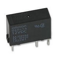
G6D-1A-ASI 12DC
Description
RELAY, PCB, SPNO, 12VDC
Manufacturer
Omron
Datasheet
1.G6D-1A-ASI_24DC.pdf
(4 pages)
Specifications of G6D-1A-ASI 12DC
Relay Type
Power
Coil Voltage Vdc Nom
12V
Contact Current Max
5A
Contact Voltage Ac Nom
250V
Contact Voltage Dc Nom
30V
Coil Resistance
720ohm
Coil Type
DC Coil
Coil Current
16.7mA
Nom Operating
RoHS Compliant
Contact Configuration
SPNO
Rohs Compliant
Yes


G6D
■
Note:
■
Engineering Data
2
Rated load
Rated carry current
Max. switching voltage
Max. switching current
Max. switching power
Failure rate (reference value)
Contact resistance
Operate time
Release time
Insulation resistance
Dielectric strength
Impulse withstand voltage
Vibration resistance
Shock resistance
Endurance
Ambient temperature
Ambient humidity
Weight
Maximum Switching Power
Ambient Temperature vs.
Operating/Recovery Voltage
G6D-1A-ASI
100
0.5
0.3
0.1
50
30
10
80
60
40
20
Contact Ratings
Characteristics
−40
5
3
1
0
0
Sample: G6D1A
Quantity: 5
P level:
−20
3
DC resistive
load
DC inductive
load
5
10
0
Ambient temperature (°C)
λ
60
30
Switching voltage (V)
20
AC inductive
load
cosφ=0.4
= 0.1 x 10
AC resistive load
100
Operating voltage
Recovery voltage
40
250 500 1,000
60
–6
max.
min.
max.
min.
/operation
X
X
80
5 A at 250 VAC, 5 A at 30 VDC, resistive load
5 A
250 VAC, 30 VDC
5 A
1,250 VA, 150 W
10 mA at 5 VDC
100 m Ω max.
10 ms max.
5 ms max.
1,000 M Ω min. (at 500 VDC)
3,000 VAC, 50/60 Hz for 1 min between coil and contacts
750 VAC, 50/60 Hz for 1 min between contacts of same polarity
6,000 V (1.2 x 50 µs) between coil and contacts
Destruction: 10 to 55 to 10 Hz, 0.75-mm single amplitude (1.5-mm double amplitude)
Malfunction: 10 to 55 to 10 Hz, 0.75-mm single amplitude (1.5-mm double amplitude)
Destruction: 1,000 m/s
Malfunction: 100 m/s
Mechanical: 20,000,000 operations min. (at 18,000 operations/hr)
Electrical:
Operating: − 25°C to 70°C (with no icing)
Operating: 5% to 85%
Approx. 3 g
Not energized
Measurement conditions: Impose a shock in the
±X, ±Y, and ±Z directions three times each with
the Relay energized to check the shock values
that cause the Relay to malfunction.
X
Z'
Endurance
Malfunctioning Shock
G6D-1A-ASI
500
300
100
50
30
10
3
5
0
Energized
250-VAC/30 VDC inductive load
(cosφ=0.4/ L/R=7 ms)
1
70,000 operations min. (5 A at 250 VAC/30 VDC, resistive load)
300,000 operations min. (2 A at 250 VAC/30 VDC, resistive load)
2
250-VAC/30-VDC resistive load
Y
Y'
3
1,000
800
600
400
200
206
4
2
Unit: m/s
2
Switching current (A)
5
6
2
Z
X'
7
Y
Y'
Shock direction
8
X
Coil terminals
9
10
X'
Z
Z'
Ambient Temperature vs.
Maximum Coil Voltage
Note: The maximum coil voltage is the
200
180
160
140
120
100
80
60
0
maximum voltage that can be
applied to the relay coil
23 30
40
Ambient temperature (°C)
50
60
70
80
90
G6D
Related parts for G6D-1A-ASI 12DC
Image
Part Number
Description
Manufacturer
Datasheet
Request
R

Part Number:
Description:
RELAY SPST 5A 5VDC PC MT
Manufacturer:
Omron
Datasheet:
Part Number:
Description:
RELAY SPST 5A 24VDC PC MT
Manufacturer:
Omron
Datasheet:

Part Number:
Description:
RELAY SPST 5A 12VDC PC MNT
Manufacturer:
Omron
Datasheet:
Part Number:
Description:
RELAY SPST 5A 12VDC PC MT
Manufacturer:
Omron
Datasheet:

Part Number:
Description:
Power PCB Relay
Manufacturer:
Omron
Datasheet:
Part Number:
Description:
Power PCB Relay
Manufacturer:
Omron
Datasheet:
Part Number:
Description:
POWER PCB RELAY
Manufacturer:
Omron
Datasheet:
Part Number:
Description:
POWER PCB RELAY
Manufacturer:
Omron
Datasheet:

Part Number:
Description:
POWER RELAY, SPST-NO, 24VDC, 5A PC BOARD
Manufacturer:
Omron
Datasheet:
Part Number:
Description:
RELAY POWER PCB
Manufacturer:
Omron
Datasheet:

Part Number:
Description:
Manufacturer:
Omron Corporation
Datasheet:
Part Number:
Description:
Power PCB Relay
Manufacturer:
Omron
Datasheet:
Part Number:
Description:
Power PCB Relay
Manufacturer:
Omron
Datasheet:
Part Number:
Description:
Terminal Relay - 4 Output
Manufacturer:
Omron
Datasheet:

Part Number:
Description:
TERMINAL RELAY - 4 OUTPUT
Manufacturer:
Omron
Datasheet: