G5CA-1AE 12DC Omron, G5CA-1AE 12DC Datasheet - Page 4
G5CA-1AE 12DC
Manufacturer Part Number
G5CA-1AE 12DC
Description
RELAY, PCB, SPNO, 12VDC
Manufacturer
Omron
Datasheet
1.G5CA-1AE_12DC.pdf
(4 pages)
Specifications of G5CA-1AE 12DC
Relay Type
Power
Coil Voltage Vdc Nom
12V
Contact Current Max
15A
Contact Voltage Ac Nom
110V
Contact Voltage Dc Nom
30V
Coil Resistance
720ohm
Coil Type
DC Coil
Coil Current
16.7mA
Nom Operating
RoHS Compliant
Contact Configuration
SPST
Rohs Compliant
Yes


Dimensions (cont)
Precautions
■
Installation
Make sure that sufficient space is provided between relays when
installing two or more relays side by side to facilitate heat
dissipation. Insufficient heat dissipation may result in the relay
malfunctioning.
Quick-connect Terminal Connections
• Do not pass current through the PCB of the load
• The terminals are compatible with Faston receptacle #187
Note: The numbers shown in parentheses are for air-feeding
#187 terminals (width: 4.75 mm) AMP 170330-1 (170324-1)
contactterminals (quick-connect terminals).
and are suitable for positive-lock mounting.
Use only Faston terminals with the specified numbers. Select
leads for connecting Faston receptacles with wire diameters
that are within the allowable range for the load current. Do not
apply excessive force to the terminals when mounting or
dismounting the Faston receptacle.
Insert and remove terminals carefully one at a time. Do not insert
terminals on an angle, or insert/remove multiple terminals at the
same time.
The following positive-lock connectors made by AMP are
recommended. Contact the manufacturer directly for details on
connectors including availability.
Text
PCB Power Relay – G5CA
Precautions for Correct Use
Type
ALL DIMENSIONS SHOWN ARE IN MILLIMETERS.
To convert millimeters into inches, multiply by 0.03937. To convert grams into ounces, multiply by 0.03527.
AMP 170331-1 (170325-1)
AMP 170332-1 (170326-1)
Type Receptacle terminals (See note.)
Charged Terminals
The section marked with dotted circles (indicated by arrows) in
the following diagram includes the charged terminals of the relay.
When the relay is mounted on a PCB, make sure that there are no
metal patterns on the section of the PCB facing the portion of the
relay shaded in the following diagram.
Other Precautions
• The G5CA is a power relay designed for applications switching
• Use fully sealed models if the relays will require washing.
power loads such as heaters in electric household appliances.
Do not use the G5CA to switch micro loads less than 100 mA,
such as in signal applications.
Fluxprotection models may malfunction or the relay's
performance may be otherwise adversely affected if cleaning
fluid enters the relay.
AMP 172074-1 (natural color)
AMP 172074-4 (yellow)
AMP 172074-5 (green)
AMP 172074-6 (blue)
Positive housing
103
Related parts for G5CA-1AE 12DC
Image
Part Number
Description
Manufacturer
Datasheet
Request
R

Part Number:
Description:
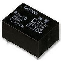
RELAY, PCB, SPNO, 24VDC
Manufacturer:
Omron
Datasheet:
Part Number:
Description:
RELAY, PCB, SPNO, 5VDC
Manufacturer:
Omron
Datasheet:

Part Number:
Description:
Power PCB Relay
Manufacturer:
Omron
Datasheet:
Part Number:
Description:
Power PCB Relay
Manufacturer:
Omron
Datasheet:
Part Number:
Description:
Power PCB Relay
Manufacturer:
Omron
Datasheet:

Part Number:
Description:
Power PCB Relay
Manufacturer:
Omron
Datasheet:
Part Number:
Description:
Power PCB Relay
Manufacturer:
Omron
Datasheet:

Part Number:
Description:
Power PCB Relay
Manufacturer:
Omron
Datasheet:

Part Number:
Description:
POWER PCB RELAY
Manufacturer:
Omron
Datasheet:
Part Number:
Description:
POWER PCB RELAY
Manufacturer:
Omron
Datasheet:
Part Number:
Description:
Power PCB Relay
Manufacturer:
Omron
Datasheet: