ALE14B12 PANASONIC EW, ALE14B12 Datasheet
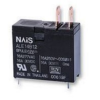
RELAY, PCB/TAB, SPNO, 12VDC

ALE14B12

Manufacturer Part Number
ALE14B12
Description
RELAY, PCB/TAB, SPNO, 12VDC
Manufacturer
PANASONIC EW
Datasheet

Specifications of ALE14B12

Relay Type
Power
Coil Voltage Vdc Nom
12V
Contact Current Max
16A
Contact Voltage Ac Nom
277V
Coil Resistance
360ohm
Coil Type
DC Coil
Coil Current
33.3mA
Nom Operating Power
400mW
Relay
RoHS Compliant
Contact Configuration
SPNO
Rohs Compliant
Yes

Available stocks

Company
Part Number
Manufacturer
Quantity
Price
Part Number:
ALE14B12
Manufacturer:
BI
Quantity:
20 000
Part Number:
ALE14B12
Manufacturer:
Matsushita
Quantity:
12 000
TYPICAL APPLICATIONS
• Microwave ovens
• Refrigerators
• OA equipment
SPECIFICATIONS
Contact
Coil
Remarks
*
*
*
*
*
*
*
*
1
2
3
4
5
6
7
8
Arrangement
Initial contact resistance, max.
(By voltage drop 6 V DC 1 A)
Contact material
Rating
(resistive load)
Expected life
(min. operations)
Nominal operating power
Measurement at same location as “Initial breakdown voltage” section.
Detection current: 10mA
Wave is standard shock voltage of 1.2
Excluding contact bounce time.
Half-wave pulse of sine wave: 11 ms; detection time: 10 s
Half-wave pulse of sine wave: 6 ms
Detection time: 10 s
Refer to 6. Usage, transport and storage conditions mentioned in NOTES
Specifications will vary with foreign standards certification ratings.
1.126
28.6
Nominal switch-
ing capacity
Max. switching
power
Max. switching
voltage
Max. switching
current
Mechanical
(at 180 cpm)
Electrical
(at 20 cpm)
(Resistive load)
12.4
.488
24.9
.980
1.126
28.6
mm
50 s according to JEC-212-1981
inch
24.9
.980
12.4
.488
16A Power Relay For
Home appliances
16 A 277 V AC
Silver alloy
4,432 V A
FEATURES
1. Ideal for magnetron and heater
loads
2. Excellent heat resistance
• This satisfies UL coil insulation class B
3. High insulation resistance
• Creepage distance and clearances
between contact and coil: Min. 8 mm
inch
• Surge withstand voltage: Min. 10,000V
4. Low operating power
• Nominal operating power: 400mW
277 V AC
ORDERING INFORMATION
1 Form A
Note: Standard packing; Carton: 100 pcs. Case 500 pcs.
400 mW
100 m
Product name
2
LE
16 A
10
10
5
6
Ex.
Contact arrangement
1: 1 Form A
A
LE
Characteristics
Max. operating speed
(at rated load)
Initial insulation resistance*
Initial breakdown
voltage*
Surge voltage between contact and
coil*
Operate time*
Release time (without diode)*
(at nominal voltage)
Temperature rise
(at nominal voltage)
Shock resistance
Vibration
resistance
Conditions for operation,
transport and storage*
(Not freezing and condens-
ing at low temperature)
Unit weight
(at nominal voltage)
2: TMP type/PCB side three terminals
3: TMP type/PCB side three terminals
4: TMP type/PCB side four terminals
5: PCB type (No tab terminals)
3
(includes one dummy terminal)
1
2
Terminal shape
4
.315
8
2
is a global brand name of Matsushita Electric Works.
Between open
contacts
Between con-
tacts and coil
Functional*
Destructive*
Functional*
Destructive
Ambient temp.
Humidity
LE-RELAYS
5. A wide variety of types
• Product line consists of 4 types with
different shapes and pins
6. Conforms to the various safety
standards:
• UL/CSA, TÜV, approved and VDE,
SEMKO pending
(
1
CSA File No. : LR26550
UL File No. : E43028
4
5
7
6
Coil insulation class
B: Class B insulation
B
Max. 55 C (resistance method, contact current
at double amplitude of 1.5mm
Min. 1,000 M (at 500 V DC)
16 A, rated coil voltage, 20 C 68°F)
Min. 1,000 m/s
1,000 Vrms for 1 min.
4,000 Vrms for 1 min.
Min. 200 m/s
Approx. 17 g
–40°F to +185°F
–40 C to +85 C
Min. 10,000 V
Approx. 20ms
Approx. 20ms
5 to 85% R.H.
10 to 55Hz
10 to 55Hz
20 cpm
12
)
Coil voltage, V DC
05: 5
06: 6
09: 9
12: 12
pending
VDE
2
2
.60 oz
{20 G}
{100 G}
18: 18
24: 24
48: 48
SEMKO
pending

Related parts for ALE14B12

ALE14B12 Summary of contents

Page 1

... Creepage distance and clearances .488 between contact and coil: Min inch 24.9 • Surge withstand voltage: Min. 10,000V .980 4. Low operating power • Nominal operating power: 400mW inch Characteristics 1 Form A Max. operating speed (at rated load) 100 m Initial insulation resistance* Silver alloy ...

Page 2

... Dimension Max. 1mm .039 inch 3mm .039 to .118 inch: Min. 3mm .118 inch: TMP type/PCB side four terminals (No tab terminals) Part No. ALE14B05 ALE14B06 ALE14B09 ALE14B12 ALE14B18 ALE14B24 ALE14B48 Nominal operating Nominal operating current, mA power 10%) 80 66.7 44.4 33.3 0.4 22.2 16 ...

Page 3

PCB side four terminals Max. 24.9 .980 3.5 .138 1.8 .071 2. PCB type PCB side four terminals (No tab terminals) Max. 24.9 .980 3.5 1.8 .138 .071 REFERENCE DATA 1. Coil temperature rise Sample: ALE15B12, 6 pcs. Point measured: ...

Page 4

... NOTES 1. Coil operating power Pure DC current should be applied to the coil. The wave form should be rectangu- lar includes ripple, the ripple factor should be less than 5%. However, check it with the actual circuit since the charac- teristics may be slightly different. 2. Voltage applied to coil To ensure reliable operation, please ap- ply nominal voltage to the coil ...

Related keywords