65.31.9.012.0300 FINDER, 65.31.9.012.0300 Datasheet
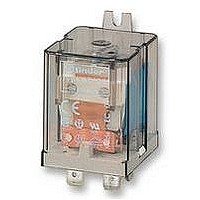
RELAY, SPST, 12VDC

65.31.9.012.0300

Manufacturer Part Number
65.31.9.012.0300
Description
RELAY, SPST, 12VDC
Manufacturer
FINDER
Datasheet

Specifications of 65.31.9.012.0300

Relay Type
Power
Coil Voltage Vdc Nom
12V
Contact Current Max
50A
Contact Voltage Ac Nom
250V
Coil Resistance
110ohm
Coil Type
DC Coil
Coil Current
109mA
Nom Operating Power
1.3W
Relay Mounting
Flange
Contact Configuration
SPST
Rohs Compliant
Yes
Lead Free Status / RoHS Status
Lead free / RoHS Compliant
20 A Power relays
1 NO + 1 NC (SPST-NO + SPST-NC)
65.31 Flange mount
65.61 PCB mount
Features
* With the AgSnO
Contact specification
Contact configuration
Rated current/Maximum peak current
Rated voltage/Maximum switching voltage V AC
Rated load AC1
Rated load AC15 (230 V AC)
Single phase motor rating (230 V AC)
Breaking capacity DC1: 30/110/220 V
Minimum switching load
Standard contact material
Coil specification
Nominal voltage (U
Rated power AC/DC
Operating range
Holding voltage
Must drop-out voltage
Technical data
Mechanical life AC/DC
Electrical life at rated load AC1
Operate/release time
Insulation between coil and contacts (1.2/50 µs) kV
Dielectric strength between open contacts
Ambient temperature range
Environmental protection
Approvals (according to type)
AC coils & DC coils
Cadmium Free option available
peak current is 120 A - 5 ms on NO contact.
(Faston 250 connections)
6.8
4.6
32.2
9.6 4.6
6.8
2
65.61
material the maximum
N
10.3
)
4.6
36.5
10.7 6.3
V AC (50/60 Hz)
4.6
VA (50 Hz)/W
mW (V/mA)
AC/DC
AC/DC
cycles
cycles
V DC
V AC
kW
AC
DC
VA
VA
ms
°C
A
A
1NO+1NC (SPST-NO+SPST-NC) 1NO+1NC (SPST-NO+SPST-NC)
20 A rated contacts
Flange mount/Faston 250
(6.3x0.8 mm) connection
9.1
6 - 12 - 24 - 48 - 60 - 110 - 120 - 230 - 240 - 400
10 · 10
32.2
14
0.8 U
0.2 U
1,000 (10/10)
(0.85…1.1)U
(0.8…1.1)U
20/0.8/0.5
21
11
3.6
–40…+75
250/400
9.1
A1
20/40*
2.2/1.3
80 · 10
AgCdO
65.31
10/12
6 - 12 - 24 - 48 - 60 - 110 - 125 - 220
5,000
1,000
1,500
N
N
1.1
RT I
6
4
/0.6 U
/0.1 U
/30 · 10
12.6
A2
14
22
3
36.5
N
13 6.3
N
N
N
6
4.6
65 Series - Power relays 20 - 30 A
20 A rated contacts
PCB mount -
bifurcated terminals
10 · 10
Copper side view
0.8 U
0.2 U
1,000 (10/10)
(0.85…1.1)U
(0.8…1.1)U
20/0.8/0.5
21
11
6.8 4.6 9.4 4.6 6.8
–40…+75
A1
250/400
A1
20/40*
2.2/1.3
80 · 10
21
11
AgCdO
65.61
10/12
5,000
1,000
1,500
32.2
N
N
1.1
RT I
6
4
/0.6 U
/0.1 U
/30 · 10
22
14
A2
A2
22
14
3
N
N
N
N
4.6
6.3
4.6
10.3
6
105
65

Related parts for 65.31.9.012.0300

65.31.9.012.0300 Summary of contents

Page 1

... Electrical life at rated load AC1 cycles Operate/release time Insulation between coil and contacts (1.2/50 µs) kV Dielectric strength between open contacts V AC Ambient temperature range Environmental protection Approvals (according to type) 65 Series - Power relays 65. rated contacts 20 A rated contacts • • Flange mount/Faston 250 PCB mount - • ...

Page 2

... Electrical life at rated load AC1 Operate/release time Insulation between coil and contacts (1.2/50 µs) kV Dielectric strength between open contacts Ambient temperature range Environmental protection Approvals (according to type) 106 65 Series - Power relays 65.31-0300 30 A rated contacts 30 A rated contacts • • Flange mount/Faston 250 PCB mount - • ...

Page 3

... Ordering information Example: 65 series power relay, PCB with bifurcated terminals (SPST-NO + SPST-NC) contact coil Series Type 3 = Faston 250 (6.3x0.8 mm) with rear flange mount 6 = PCB with bifurcated terminals No. of poles (SPST-NO + SPST-NC) Coil version (50/60 Hz Coil voltage see coil specifications Descriptions: Options and Special versions ...

Page 4

... U N 1.5 1.0 0.5 -20 - Max. permitted coil voltage Min. pick-up voltage with coil at ambient temperature. 108 65 Series - Power relays Maximum DC1 breaking capacity 0.6 0.4 limit for 1NO+1NC types 0.2 0 (A) • When switching a resistive load (DC1) having voltage and current values under the curve, an electrical life of ≥ ...

Related keywords