56.42.9.012.0000 FINDER, 56.42.9.012.0000 Datasheet - Page 3
56.42.9.012.0000
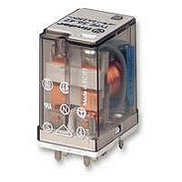
Manufacturer Part Number
56.42.9.012.0000
Description
RELAY, PCB, DPCO, 12VDC
Manufacturer
FINDER
Datasheet
1.56.32.8.230.0000.pdf
(8 pages)
Specifications of 56.42.9.012.0000
Relay Type
Power
Coil Voltage Vdc Nom
12V
Contact Current Max
20A
Contact Voltage Ac Nom
250V
Coil Resistance
140ohm
Coil Type
DC Coil
Coil Current
86mA
Nom Operating Power
1W
Relay Mounting
PC Board
Contact Configuration
DPCO
Rohs Compliant
Yes
Lead Free Status / RoHS Status
Lead free / RoHS Compliant


Ordering information
Example: 56 series plug-in relay, 2 CO (DPDT), 12 V DC coil, lockable test button and mechanical indicator.
Descriptions: Options and Special versions
Series
Type
3 = Plug-in
4 = PCB
No. of poles
2 = 2 pole, 12 A
4 = 4 pole, 12 A
Coil version
8 = AC (50/60 Hz)
9 = DC
Coil voltage
see coil specifications
Selecting features and options: only combinations in the same row are possible.
Preferred selections for best avaliability are shown in bold.
C:
LED (AC)
Type
56.32 AC
56.34 AC-DC
56.42 AC
56.44 AC-DC
Option 3, 5, 54
A1
7
Coil version A
AC
AC
DC
DC
5 6
A2
8
0 - 2 - 4
0 - 2 - 4
0 - 2 - 4
0 - 2 - 4
0 - 2 - 4
0 - 2 - 4
0 - 2 - 4
0 - 2 - 4
C:
Double LED
(DC non-polarized)
.
Option 6, 7, 74
A1
7
3
B
0
0
3
0
0
0
0 - 3
0
2
C
0 - 2 - 3 - 4 - 5 0 - 6
54
0 - 3 - 5
0 - 2 - 4 - 8 - 9 0 - 6
94
0 - 1
0
0
.
A2
8
9
C:
LED + diode (DC, polarity
positive to pin 7)
.
Option 8, 9, 94
A1
7
0 1 2
Lockable test button and mechanical flag indicator (0040)
The dual-purpose Finder test button can be used in two ways:
Case 1) The plastic pip (located directly above the test button) remains intact. In this case, when the
test button is pushed, the contacts operate. When the test button is released the contacts return to their
former state.
Case 2) The plastic pip is broken-off (using an appropriate cutting tool). In this case, (in addition to
the above function), when the test button is pushed and rotated, the contacts are latched in the
operating state, and remain so until the test button is rotated back to its former position.
In both cases ensure that the test button actuation is swift and decisive.
D
0 - 6
0 - 5 - 6 - 7 - 8
0
0
/
/
A:
0 = Standard AgNi
2 = AgCdO
4 = AgSnO
B:
0 = CO (nPDT)
3 = NO (nPST),
Contact circuit
Contact material
1.5 mm contact gap
A2
8
56 Series - Miniature power relays 12 A
.
2
D:
Rear flange mount
(56.34 only)
0
A
Special versions 6
0
B
4
C
D:
Rear 35 mm rail mount
(56.34 only)
0
D
D:
0 = Standard
5 = Top flange mount (56.34 only)
6 = Rear flange mount
7 = Top 35 mm rail mount (56.34 only)
8 = Rear 35 mm rail mount (56.34 only)
C:
0 = None
1 = Test button
2 = Mechanical indicator
3 = LED (AC)
4 = Lockable test button+mechanical indicator
5 = Lockable test button + LED (AC)
54 = Lockable test button + LED (AC) +
6 = Double LED (DC non-polarized)
7 = Lockable test button + double LED
74 = Lockable test button + double LED
8 = LED + diode (DC, polarity positive to pin 7)
9 = Lockable test button + LED + diode
94 = Lockable test button + LED + diode
Special versions 8
Options
Special versions
mechanical indicator
(DC non-polarized)
(DC non-polarized) +
mechanical indicator
(DC, polarity positive to pin 7)
(DC, polarity positive to pin 7) +
mechanical indicator
77
56
Related parts for 56.42.9.012.0000
Image
Part Number
Description
Manufacturer
Datasheet
Request
R

Part Number:
Description:
JUMPER LINK, 20WAY
Manufacturer:
FINDER
Datasheet:


Part Number:
Description:
INTERFACE RELAY, SPDT-CO, 24VAC/DC
Manufacturer:
FINDER
Datasheet:
Part Number:
Description:
INTERFACE RELAY, SPDT-CO, 24VDC
Manufacturer:
FINDER
Datasheet:

Part Number:
Description:
RELAY, SCREW TERM, 6A, 12VAC/DC
Manufacturer:
FINDER
Datasheet:
Part Number:
Description:
RELAY, SCREW TERM, 6A, 48VAC/DC
Manufacturer:
FINDER
Datasheet:
Part Number:
Description:
RELAY, SCREW TERM, 6A, 125VAC/DC
Manufacturer:
FINDER
Datasheet:
Part Number:
Description:
RELAY, SCREW TERM, 6A, 240VAC/DC
Manufacturer:
FINDER
Datasheet:
Part Number:
Description:
RELAY, SCREW TERM, 6A, 6VDC
Manufacturer:
FINDER
Datasheet:
Part Number:
Description:
RELAY, SCREW TERM, 6A, 12VDC
Manufacturer:
FINDER
Datasheet:
Part Number:
Description:
RELAY, SCRW TER, DPDT, 8A, 24VAC/DC
Manufacturer:
FINDER
Datasheet:
Part Number:
Description:
RELAY, SCREW TERM, DPDT, 8A, 12VDC
Manufacturer:
FINDER
Datasheet:
Part Number:
Description:
RELAY, SCREW TERM, DPDT, 8A, 24VDC
Manufacturer:
FINDER
Datasheet:

Part Number:
Description:
RELAY, SCREWLESS, 6A, 24VDC
Manufacturer:
FINDER
Datasheet: