56.32.9.024.0000 FINDER, 56.32.9.024.0000 Datasheet

RELAY, DPCO, 24VDC

56.32.9.024.0000

Manufacturer Part Number
56.32.9.024.0000
Description
RELAY, DPCO, 24VDC
Manufacturer
FINDER
Datasheet

Specifications of 56.32.9.024.0000

Relay Type
Power
Coil Voltage Vdc Nom
24V
Contact Current Max
20A
Contact Voltage Ac Nom
250V
Coil Resistance
640ohm
Coil Type
DC Coil
Coil Current
40mA
Nom Operating Power
1W
Relay Mounting
Plug-In
Contact Configuration
DPCO
Rohs Compliant
Yes
Lead Free Status / RoHS Status
Lead free / RoHS Compliant
Plug-in
12 A Power relay, 2 & 4 pole
Features
* For 4 CO (4PDT) only.
Contact specification
Contact configuration
Rated current/Maximum peak current
Rated voltage/Maximum switching voltage V AC
Rated load AC1
Rated load AC15 (230 V AC)
Single phase motor rating (230 V AC)
Breaking capacity DC1: 30/110/220 V
Minimum switching load
Standard contact material
Coil specification
Nominal voltage (U
Rated power AC/DC
Operating range
Holding voltage
Must drop-out voltage
Technical data
Mechanical life AC/DC
Electrical life at rated load AC1
Operate/release time
Insulation between coil and contacts (1.2/50 µs) kV
Dielectric strength between open contacts
Ambient temperature range
Environmental protection
Approvals (according to type)
Flange mount option -
(Faston 187, 4.8x0.5 mm termination)
AC coils & DC coils
Lockable test button and mechanical flag
indicator - standard on 2 pole types
Cadmium Free contacts
(preferred version)
Contact material options
96 series sockets, coil EMC suppression,
accessories
N
)
V AC (50/60 Hz)
VA (50 Hz)/W
mW (V/mA)
AC/DC
AC/DC
cycles
cycles
V DC
V AC
kW
AC
DC
VA
VA
ms
°C
A
A
6-12-24-48-60-110-125-220
2 pole changeover contact
Plug-in/Faston 187
20.7
10
20 · 10
0.8 U
12/0.25/0.12
0.2 U
(0.8…1.1)U
(0.8…1.1)U
2 CO (DPDT)
500 (10/5)
A1
1
–40…+70
7
250/400
200 · 10
56.32
5
12/20
3,000
1.5/1
1,000
3
AgNi
0.55
500
N
8/8
RT I
N
2 4
6
4
/0.6 U
/50 · 10
/0.1 U
6
A2
7.25
8
27.7
5.9 4.753.85
3
N
N
6 - 12 - 24 - 48 - 60 - 110 - 120 - 230 - 240 - 400*
N
N
56 Series - Miniature power relays 12 A
6
2 pole normally open
contact (1.5 mm gap)
Plug-in/Faston 187
2 NO (DPST-NO) - 1.5 mm
20.7
10
(0.85…1.1)U
56.32-0300
12/0.6/0.3
0.85 U
500 (10/5)
20 · 10
A1
0.2 U
7
–40…+70
250/400
200 · 10
5
1.5/—
12/20
3,000
2,000
3
AgNi
0.55
500
8/4
RT I
4
6
N
A2
4
8
7.25
N
/—
6
27.7
/—
/—
5.9 8.6
3
N
6-12-24-48-60-110-125-220
4 pole changeover contact
Plug-in/Faston 187
10
20 · 10
41
10
0.8 U
1
12/0.25/0.12
(0.85…1.1)U
0.2 U
(0.8…1.1)U
4 CO (4PDT)
9
500 (10/5)
5
–40…+70
10
250/400
150 · 10
13
A1
2 6
56.34
12/20
3,000
1,000
2/1.3
AgNi
10
0.55
500
N
8/8
N
RT I
6
/0.6 U
/50 · 10
5
/0.1 U
3 7
11
14
A2
4 8
3
7.25
12
N
27.8
N
N
N
5.9 4.75 3.85
6
75
56

Related parts for 56.32.9.024.0000

56.32.9.024.0000 Summary of contents

Page 1

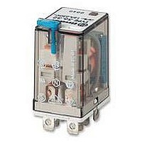
... Features Plug- Power relay, 2 & 4 pole Flange mount option - • (Faston 187, 4.8x0.5 mm termination) AC coils & DC coils • Lockable test button and mechanical flag • indicator - standard on 2 pole types Cadmium Free contacts • (preferred version) Contact material options • 96 series sockets, coil EMC suppression, • ...

Page 2

... Operate/release time Insulation between coil and contacts (1.2/50 µs) kV Dielectric strength between open contacts Ambient temperature range Environmental protection Approvals (according to type Series - Miniature power relays 12 A 56.42 2 pole normally open contact • 2 pole changeover contact • (1.5 mm gap) PCB mount • ...

Page 3

... Lockable test button and mechanical flag indicator (0040) The dual-purpose Finder test button can be used in two ways: Case 1) The plastic pip (located directly above the test button) remains intact. In this case, when the test button is pushed, the contacts operate. When the test button is released the contacts return to their former state ...

Page 4

... In the case of DC13 loads, the connection of a diode in parallel with the load will permit a similar electrical life as for a DC1 load. Note: the release time of the load will increased Series - Miniature power relays 12 A insulation rated voltage rated impulse withstand voltage ...

Page 5

... coil operating range v ambient temperature 4 pole relay U 2 1.5 1.0 0.5 -20 - Max. permitted coil voltage Min. pick-up voltage with coil at ambient temperature. 56 Series - Miniature power relays coil data, 2 pole relay Resistance Rated coil Nominal Coil consumption voltage code Ω 150 6 8.006 ...

Page 6

... Accessories Adaptor with top mount flange for 56.32.x.xxx.xx00 056.05 15 056.05 with relay Series - Miniature power relays 12 A 3.6 2 34.3 1.7 056.05 ...

Page 7

... LED + Varistor LED + Varistor Green LED is standard. LED + Varistor Red LED available on request. RC circuit RC circuit RC circuit Residual current by-pass (62 kΩ/1W) 96 Series - Sockets and accessories for 56 series relays 96.72 (blue) 56. 250 V ≥ °C –40…+ solid wire mm ...

Page 8

... A1 13 Packaging code How to code and identify retaining clip and packaging options for sockets. Code options according to the last three letters Series - Sockets and accessories for 56 series relays °C –40…+70 21.5 21 Copper side view 96. Copper side view 96 ...

Related keywords