W67RCSX-12 Magnecraft / Schneider Electric, W67RCSX-12 Datasheet - Page 38
W67RCSX-12
Manufacturer Part Number
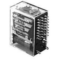
W67RCSX-12
Description
POWER RELAY, 6PDT, 12VDC, 5A, PLUG IN
Manufacturer
Magnecraft / Schneider Electric
Specifications of W67RCSX-12
Relay Type
Miniature
Coil Voltage Vdc Nom
12V
Contact Current Max
5A
Contact Voltage Ac Nom
120V
Contact Voltage Dc Nom
28V
Coil Resistance
90ohm
Contact Configuration
6PDT
Coil Type
DC
Contact Form
6PDT
Current, Rating
5 A
Diameter, Mounting
1.5 in. (± 0.5 in.)
Dielectric Rating
1500 V (RMS) (Coil to Contacts), 1000 V (RMS) (Across Open Contacts, Pole to Pole, Contacts to Frame)
Dimensions
1.374 in. L x 0.73 in. W (Max.)
Function
Power
Material, Contact
Silver Alloy
Mounting Type
Socket
Power, Rating
0.5 W
Resistance, Coil
90 Ohms
Standards
cULus
Temperature, Operating, Maximum
60 °C
Temperature, Operating, Minimum
-40 °C
Termination
Plug-In
Voltage, Control
12 VDC
Voltage, Rating
240 VAC
Lead Free Status / RoHS Status
Lead free / RoHS Compliant


CLASS
1...
COIL
CONTACTS
DIELECTRIC STRENGTH
TEMPERATURE
LIFE EXPECTANCY
MISCELLANEOUS
GENERAL
GENERAL
Across Open Contacts:
Pull-in Voltage:
Dropout Voltage:
Resistance:
Coil Power:
Insulation System:
Maximum Coil Dissipation:
Duty:
Contact material:
Contact Resistance:
Contact Ratings:
Contacts to Coil:
Pole to Pole:
Contacts to Frame:
Insulation Resistance:
Operating:
Storage
Electrical:
Mechanical:
Operating Position:
Insulation material:
Enclosure:
Terminals:
Weight:
37
BENEFITS OF 3mm CONTACT GAP DESIGN:
1. HIGH DIELECTRIC STRENGTH ACROSS CONTACTS.
2. IMPROVED ARC QUENCHING WHEN BREAKING HIGH CURRENT LOADS.
3. MEETS EUROPEAN SPACING REQUIREMENTS OF 8mm ACROSS SURFACES
3 POLES
POLES
1 POLE
THRU
388V
HORSE POWER
UL CONTACT LOAD RATINGS TABLE
CURRENT OR
15 AMP
15 AMP
1/3 HP
1/2 HP
SPECIFICA
SPECIFICA
HIGH VOLTAGE PLUG-IN & FLANGE MOUNT RELAY
120/240 VAC
PHONE: (843) 393-5778 FAX: (843) 393-4123 EMAIL: info@magnecraft.com
80% of nominal voltage or less for DC coils
85% of nominal voltage or less for AC coils
10% of nominal voltage or more
±10% measured at 25˚C
1.2 watts for DC coils, 2 VA to 2.75 VA for AC @ 25˚C
Class “B” (130˚C per UL standard 1446)
3.0 watts max. DC
Continuous
Silver alloy, gold flashed
50 milliohms maximum initial resistance at rated current
See “UL CONTACT LOAD RATINGS TABLE”
3 mm gap, 4000 V rms
3 mm gap, 1000 V rms
2000 V rms
2000 V rms
1000 megohms @ 500 VDC
-30˚C to +50˚C. (AC), -30˚C to +65˚C. (DC)
-30˚C to +100˚C
100,000 operations @ rated resistive load
Any
Molded plastic
Polycarbonate dust cover
0.187 x 0.032 quick connect flange or 0.187 x 0.020
solder/plug-in. Optional printed circuit terminals available
88 grams approx.
VOLTAGE
5,000,000 operations @ no load
120 VAC
240 VAC
28 VDC
LOAD
TIONS
TIONS
LOAD VOLTAGE
FREQUENCY
50/60 Hz
50/60 Hz
50/60 Hz
DC
RESISTIVE
RESISTIVE
TYPE OF
MOTOR
MOTOR
LOAD
WHEN USED WITH
SOCKET 70-463-1
CURRENT LIMITED TO
RATING OF RELAY OR
SOCKET WHICHEVER
IS LESS
C
Mating Sockets
70-463-1: SCREW/DIN
70-124-1: SOLDER
70-178-1, 70-178-2: PRINTED CIRCUIT
70-124-2: QUICK CONNECT
See section 8, page 16, 17
DPST-NO, 3PST-NO, 15 AMPS
US
LISTED 367G
IND. CONT. EQ.
MANUFACTURED UNDER
ISO 9002 & QS 9000
UL Recognized
File No. E43641
c
OPTIONAL FLANGE MOUNT COVER
OPTIONAL DIN MOUNT COVER
*
*
*
COMPLIES WITH REQUIREMENTS OF
IEC = INTERNATIONAL
ELECTROTECHNICAL COMMISSION
CE TESTING AND EVALUATION
PERFORMED BY THE UNDERWRITERS
LABORATORIES AS A THIRD PARTY
PARTICIPANT
us
PLUG-IN
IEC STANDARDS 947-4-1 AND
947-5-1 LOW VOLTAGE DIRECTIVE
168986
Related parts for W67RCSX-12
Image
Part Number
Description
Manufacturer
Datasheet
Request
R

Part Number:
Description:
POWER RELAY, 6PDT, 24VDC, 5A, PLUG IN
Manufacturer:
Magnecraft / Schneider Electric
Datasheet:
Part Number:
Description:
POWER RELAY, DPDT, 12VDC, 5A, PLUG IN
Manufacturer:
Magnecraft / Schneider Electric
Datasheet:
Part Number:
Description:
POWER RELAY, DPDT, 24VDC, 5A, PLUG IN
Manufacturer:
Magnecraft / Schneider Electric
Datasheet:
Part Number:
Description:
POWER RELAY, 4PDT, 12VDC, 5A, PLUG IN
Manufacturer:
Magnecraft / Schneider Electric
Datasheet:
Part Number:
Description:
POWER RELAY, 4PDT, 24VDC, 5A, PLUG IN
Manufacturer:
Magnecraft / Schneider Electric
Datasheet:
Part Number:
Description:
POWER RELAY, DPDT, 5VDC, 5A, PLUG IN
Manufacturer:
Magnecraft / Schneider Electric
Datasheet:

Part Number:
Description:
Solid State Relays 3A/50VAC SPST-NO
Manufacturer:
Magnecraft / Schneider Electric
Datasheet:

Part Number:
Description:
HEAT SINK MAGNECRAFT
Manufacturer:
Magnecraft / Schneider Electric
Datasheet:

Part Number:
Description:
Bracket, Panel Mounting; Use with 711, 712, TDRSRX/SOX Series Magnecraft Relays
Manufacturer:
Magnecraft/Schneider Electric
Datasheet:
Part Number:
Description:
Bracket, DIN Rail Mounting; Use with 711, 712, TDRSRX/SOX Series Magnecraft Relays
Manufacturer:
Magnecraft/Schneider Electric
Datasheet:

Part Number:
Description:
Solid State Relays SPST-NO 48 to 480 VAC
Manufacturer:
Magnecraft / Schneider Electric
Datasheet:
Part Number:
Description:
Solid State Relays SPST-NO 48 to 480 VAC
Manufacturer:
Magnecraft / Schneider Electric
Datasheet:
Part Number:
Description:
Solid State Relays SPST-NO 3 to 50 VDC
Manufacturer:
Magnecraft / Schneider Electric
Datasheet:
Part Number:
Description:
Solid State Relays SPST-NO 48 to 600 VAC
Manufacturer:
Magnecraft / Schneider Electric
Datasheet:
Part Number:
Description:
Relay; E-Mech; Power; On Delay; SPDT; Cur-Rtg 15A; Ctrl-V 120AC; Vol-Rtg 240/24AC/DC
Manufacturer:
Magnecraft/Schneider Electric
Datasheet: