G7L-2A-TUB-J-CB-AC100 Omron, G7L-2A-TUB-J-CB-AC100 Datasheet - Page 13
G7L-2A-TUB-J-CB-AC100
Manufacturer Part Number
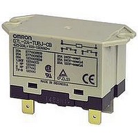
G7L-2A-TUB-J-CB-AC100
Description
POWER RELAY DPST-NO 100VAC, 25A, BRACKET
Manufacturer
Omron
Datasheet
1.G7L-2A-BUB-J-CB-DC12.pdf
(13 pages)
Specifications of G7L-2A-TUB-J-CB-AC100
Relay Type
High Capacity
Coil Voltage Vac Nom
100V
Contact Current Max
25A
Contact Voltage Ac Nom
220V
Coil Resistance
5260ohm
Contact Configuration
DPST-NO
Coil Type
AC
Lead Free Status / RoHS Status
Lead free / RoHS Compliant


Precautions
Refer to page 11 for general precautions.
■ Installation
• Although there are not specific limits on the installation site, it
• PCB Terminal-equipped Relays weigh approximately 100 g. Be
• Quick-connect terminals can be connected to Faston receptacle
• Allow suitable slack on leads when wiring, and do not subject the
• Mounting torque (upper-bracket models): 0.98 N·m
• G7L Relays with test buttons must be mounted facing down.
• Be careful not to touch the test button accidentally. Doing so may
• Be sure to use the test button for test purposes only (with test-but-
■ Cleaning PCB Terminals
• PCB terminals have flux-tight construction which prevents flux from
■ Connecting
• Refer to the following table when connecting a wire with a crimp-
Tightening torque: Coil:
Coil
Contact
Cat. No. J055-E1-04A
should be as dry and dust-free as possible.
sure that the PCB is strong enough to support them. We recom-
mend dual-side through-hole PCBs to reduce solder cracking from
heat stress.
#250 and positive-lock connectors.
terminals to excessive force.
turn ON the contact.
ton models). The test button is used for Relay circuit tests, such as
circuit continuity tests. Do not attempt to switch the load with the
test button.
penetrating into the Relay base housing, e.g., due to capillary
action up the terminals when Relay is soldered onto the PCB. This
type of Relay cannot be immersed for cleaning.
style terminal to the G7L.
Terminals
ALL DIMENSIONS SHOWN ARE IN MILLIMETERS.
To convert millimeters into inches, multiply by 0.03937. To convert grams into ounces, multiply by 0.03527.
Screw terminals
Contact: 1.37 N·m
M3.5
M4
9.3
8
0.98 N·m
5.5
5.8
6.5
5
In the interest of product improvement, specifications are subject to change without notice.
Front-connecting
M3.5
M4
Socket
9.3
8
6.5
5.3
5.5
7
■ Rated Current Flow
When using B-series (screw) products, the rated current from the
screw terminals (M4) should be 20 A or less according to jet stan-
dard (electrical appliance and material control law of Japan).
■ Minute Loads
The G7L is used for switching power loads, such as motor, trans-
former, solenoid, lamp, and heater loads. Do not use the G7L for
switching minute loads, such as signals.
■ Operating Coil
If a transistor drives the G7L check the leakage current, and connect
a bleeder resistor if necessary.
The AC coil is provided with a built-in full-wave rectifier. If a triac,
such as an SSR, drives the G7L, the G7L may not release. Be sure
to perform a trial operation with the G7L and the triac before applying
them to actual use.
■ DIN Track Mounting Adapter
DIN Track Mounting
• Use a DIN-conforming 50-cm track or 1-m track (both are sold sep-
• The DIN Track Mounting Adapter and Front-connecting Socket can
• To support the G7L mounted on a DIN Track Mounting Adapter or
Screw Mounting
• Screw-mount the DIN Track Mounting Adapter or Front-connecting
• When cutting or opening holes on the panel after the Front-con-
arately) for mounting a number of G7L Relays.
Cut and shorten the track to an appropriate length it if the required
track length is less than 50 cm.
be mounted on the G7L with just one hand and dismounted with
ease by using a screwdriver.
Front-connecting Socket, use the PFP-M End Plate. Put the End
Plate onto the DIN Track Mounting Adapter or Front-connecting
Socket so that the surface mark of the End Plate faces upwards.
Then tighten the screw of the End Plate securely with a screw-
driver.
Socket securely after opening screw mounting holes on them.
necting Socket is mounted, take proper measures so that the cut-
ting chips will not fall onto the Relay terminals. When cutting or
opening holes on the upper part of the panel, mask the Front-con-
necting Socket properly with a cover.
and Front-connecting Socket
Power Relay
G7L
187
Related parts for G7L-2A-TUB-J-CB-AC100
Image
Part Number
Description
Manufacturer
Datasheet
Request
R

Part Number:
Description:
RELAY
Manufacturer:
Omron
Datasheet:

Part Number:
Description:
RELAY
Manufacturer:
Omron
Datasheet:

Part Number:
Description:
RELAY
Manufacturer:
Omron
Datasheet:

Part Number:
Description:
RELAY
Manufacturer:
Omron
Datasheet:
Part Number:
Description:
RELAY
Manufacturer:
Omron
Datasheet:
Part Number:
Description:
RELAY
Manufacturer:
Omron
Datasheet:
Part Number:
Description:
RELAY
Manufacturer:
Omron
Datasheet:
Part Number:
Description:
RELAY
Manufacturer:
Omron
Datasheet:
Part Number:
Description:
RELAY
Manufacturer:
Omron
Datasheet:
Part Number:
Description:
RELAY
Manufacturer:
Omron
Datasheet:

Part Number:
Description:
POWER RELAY DPST-NO 240VAC, 25A, BRACKET
Manufacturer:
Omron
Datasheet:
Part Number:
Description:
RELAY
Manufacturer:
Omron
Datasheet:
Part Number:
Description:
RELAY
Manufacturer:
Omron
Datasheet:
Part Number:
Description:
RELAY
Manufacturer:
Omron
Datasheet: