G5CA-1A-DC24 Omron, G5CA-1A-DC24 Datasheet - Page 4
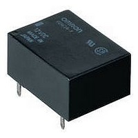
G5CA-1A-DC24
Manufacturer Part Number
G5CA-1A-DC24
Description
POWER RELAY SPST-NO 24VDC, 10A, PC BOARD
Manufacturer
Omron
Datasheet
1.G5CA-1A-DC12.pdf
(4 pages)
Specifications of G5CA-1A-DC24
Relay Type
General Purpose
Coil Voltage Vdc Nom
24V
Contact Current Max
10A
Contact Voltage Ac Nom
250V
Contact Voltage Dc Nom
30V
Coil Resistance
2880ohm
Contact Configuration
SPST-NO
Lead Free Status / RoHS Status
Lead free / RoHS Compliant
Available stocks
Company
Part Number
Manufacturer
Quantity
Price
Company:

Part Number:
G5CA-1A-DC24V
Manufacturer:
OMRON
Quantity:
12 000


G5CA
Precautions
■
Installation
Make sure that sufficient space is provided between relays when
installing two or more relays side by side to facilitate heat dissipa-
tion. Insufficient heat dissipation may result in the relay malfunc-
tioning.
Quick-connect Terminal Connections
• Do not pass current through the PCB of the load contact termi-
• The terminals are compatible with Faston receptacle #187 and
Note
OMRON RELAY & DEVICES Corporation
C&C Power Relay Division
Marketing Department
1110 Sugi, Yamaga-City,
Kumamoto, 861-0596 Japan
Tel: (81)968-44-4160/Fax: (81)968-44-4107
4
Cat. No. J151-E1-01
G5CA-1A-TP-E
#187 terminals
(width: 4.75 mm)
nals (quick-connect terminals).
are suitable for positive-lock mounting.
Use only Faston terminals with the specified numbers. Select
leads for connecting Faston receptacles with wire diameters that
are within the allowable range for the load current. Do not apply
excessive force to the terminals when mounting or dismounting
the Faston receptacle.
Insert and remove terminals carefully one at a time. Do not insert
terminals on an angle, or insert/remove multiple terminals at the
same time.
The following positive-lock connectors made by AMP are recom-
mended. Contact the manufacturer directly for details on con-
nectors including availability.
Precautions for Correct Use
Type
The numbers shown in parentheses are for air-feeding.
Pitch:
2.54 mm × 4 min.
between terminals
AMP 170330-1 (170324-1)
AMP 170331-1 (170325-1)
AMP 170332-1 (170326-1)
ALL DIMENSIONS SHOWN ARE IN MILLIMETERS.
To convert millimeters into inches, multiply by 0.03937. To convert grams into ounces, multiply by 0.03527.
Receptacle terminals
(10.9)*
3.6
11
Pitch: 2.54 mm × 3 min. between terminals
(See note.)
In the interest of product improvement, specifications are subject to change without notice.
0.3
16.1
25.1max.
(24.9)*
1
AMP 172074-1 (natural color)
AMP 172074-4 (yellow)
AMP 172074-5 (green)
AMP 172074-6 (blue)
4.8
5
Positive housing
* Average value
1.35
1.3 dia.
3.2
0.3
6.35
4.9
13.3
10˚
22.1max.
14.25
(21.9)*
±1˚
17.78
Charged Terminals
The section marked with dotted circles (indicated by arrows) in
the following diagram includes the charged terminals of the relay.
When the relay is mounted on a PCB, make sure that there are no
metal patterns on the section of the PCB facing the portion of the
relay shaded in the following diagram..
Other Precautions
• The G5CA is a power relay designed for applications switching
• Use fully sealed models if the relays will require washing. Flux-
0.5
0.5
power loads such as heaters in electric household appliances.
Do not use the G5CA to switch micro loads less than 100 mA,
such as in signal applications.
protection models may malfunction or the relay's performance
may be otherwise adversely affected if cleaning fluid enters the
relay.
0.6
17.78
1.6
Charged
terminals
Mounting Holes
(BOTTOM VIEW)
Tolerance: ±0.1 mm
Two, 1 dia.
16.1
21.1
5
1.8
8
Four, 1.2 dia.
elliptic holes
Terminal Arrangement/
Internal Connections
6.25
6.5
14.25
Printed in Japan
0804-?M (0804) (?)
(No coil polarity)
(BOTTOM VIEW)
12.7
0.18
(BOTTOM VIEW)
(TOP VIEW)
2
1
G5CA
4
3
Related parts for G5CA-1A-DC24
Image
Part Number
Description
Manufacturer
Datasheet
Request
R

Part Number:
Description:
Power PCB Relay
Manufacturer:
Omron
Datasheet:
Part Number:
Description:
Power PCB Relay
Manufacturer:
Omron
Datasheet:
Part Number:
Description:
Power PCB Relay
Manufacturer:
Omron
Datasheet:

Part Number:
Description:
Power PCB Relay
Manufacturer:
Omron
Datasheet:
Part Number:
Description:
Power PCB Relay
Manufacturer:
Omron
Datasheet:

Part Number:
Description:
Power PCB Relay
Manufacturer:
Omron
Datasheet:

Part Number:
Description:
POWER PCB RELAY
Manufacturer:
Omron
Datasheet:
Part Number:
Description:
POWER PCB RELAY
Manufacturer:
Omron
Datasheet:
Part Number:
Description:
POWER PCB RELAY
Manufacturer:
Omron
Datasheet:
Part Number:
Description:
POWER PCB RELAY
Manufacturer:
Omron
Datasheet:
Part Number:
Description:
POWER PCB RELAY
Manufacturer:
Omron
Datasheet:
Part Number:
Description:
POWER PCB RELAY
Manufacturer:
Omron
Datasheet:
Part Number:
Description:
Power PCB Relay
Manufacturer:
Omron
Datasheet: