841CS5-UNI Magnecraft / Schneider Electric, 841CS5-UNI Datasheet

CURRENT SENSING RELAY, SPDT, 0.5-5A

841CS5-UNI

Manufacturer Part Number
841CS5-UNI
Description
CURRENT SENSING RELAY, SPDT, 0.5-5A
Manufacturer
Magnecraft / Schneider Electric
Series
841r
Datasheets

Specifications of 841CS5-UNI

Contact Configuration
SPDT
Power Consumption
1.5VA
Supply Voltage Max
240VAC
Supply Current Max
5A
Relay Mounting
DIN Rail
Control Voltage
240VAC
Coil Voltage Vac Nom
240V
Display Type
Time-Delay Relay
Supply Voltage
24 V to 240 V
Contact Form
SPDT
Termination Style
Quick Connect
Function
Current
Output
Current
Range, Measurement
5 A
Technology
Inductive
Voltage, Supply
24-240 VAC
No. Of Poles
1
Rohs Compliant
Yes
Carry Current
5A
Lead Free Status / RoHS Status
Lead free / RoHS Compliant
Time Delay Relays – Application Data
Definition:
Time Delay is defined as the controlled period between the functioning of two events. A Time Delay relay is a combination
of an electromechanical output relay and a control circuit. The control circuit is comprised of solid state components and
timing circuits that control operation of the relay and timing range. Typical time delay functions include On-Delay, Repeat
cycle (starting off), Interval, Off-Delay, Retriggerable One Shot, Repeat cycle (starting on), Pulse Generator, One Shot,
On/Off Delay, and Memory Latch. Each function is explained in the table below. Time delay relays have a broad
choice of timing ranges from less than one second to many days. There are many choices of timing adjustments from
calibrated external knobs, DIP switches, thumbwheel switches, or recessed potentiometer. The output contacts on the
electromechanical output relay are direct wired to the output terminals. The contact load ratings are specified for each
specific type of time delay relay.
Understanding the differences between all the functions available in time delay relays can sometimes be a daunting task.
When designing circuits using time delay relays questions such as:
“What initiates a time delay relay?”
“Does the timing start with the application or release of voltage?”
“When does the output relay come on?”
must be asked.
Time delay relays are simply control relays with a time delay built in. Their purpose is to control an event based on time.
The difference between relays and time delay relays is when the output contacts open & close: on a control relay, it
happens when voltage is applied and removed from the coil; on time delay relays, the contacts will open or close before
or after a pre-selected, timed interval.
Typically, time delay relays are initiated or triggered by one of two methods:
• application of input voltage (On Delay, Interval On, Flasher, Repeat Cycle, Delayed Interval & Interval/Flasher).
• opening or closing of a trigger signal (Off Delay, Single Shot & Watchdog).
These trigger signals can be one of two designs:
• a control switch (dry contact), i.e., limit switch, push button, float switch, etc.
• voltage (commonly known as a power trigger).
To help understand, some definitions are important:
Input Voltage: Control voltage applied to the input terminals (see wiring diagrams below). Depending on the function,
input voltage will either initiate the unit or make it ready to initiate when a trigger signal is applied.
Trigger Signal: On certain timing functions, a trigger signal is used to initiate the unit after input voltage has been applied.
As noted above, this trigger signal can either be a control switch (dry contact switch) or a power trigger (voltage).
Output (Load): Every time delay relay has an internal relay (usually mechanical) with contacts that open & close to control
the load. They are represented by the dotted lines in the wiring diagrams. Note that the user must provide the voltage to
power the load being switched by the output contacts of the time delay relay.
The following tables contain both written and visual descriptions on how the common timing functions operate. A Timing
Chart shows the relationship between Input Voltage, Trigger Signal (if present) and Output Contacts.
5/2
M agne cr aft S olu tion Guide 1 0 5 A

Related parts for 841CS5-UNI

841CS5-UNI Summary of contents

Page 1

... Time delay relays are simply control relays with a time delay built in. Their purpose is to control an event based on time. The difference between relays and time delay relays is when the output contacts open & close control relay, it happens when voltage is applied and removed from the coil ...

Page 2

FUNCTION DEFINITION TABLES Function Operation A. When the input voltage U is applied, timing delay t begins. Relay contacts R change state after time delay is complete. Contacts return to their shelf state ON DELAY Power On when power U ...

Page 3

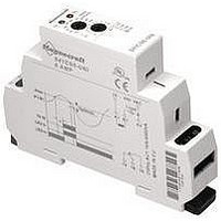
Advantages of the 841 Current Sensing Relay Input Indication Green LED Light. Input Terminals Accepts AWG Wire. 5/10 Output Indication Red LED Light. Current Sensing Adjustment Knob Sense Anywhere from 10% to 100% of the Rated ...

Page 4

The 841 Current Sensor Series is a complete current sensing solution in one modular package which mounts directly to a DIN rail. This product allows the user to monitor the current of one circuit ( amps) and switch ...

Page 5

... UL, CE °C -30…+70 °C -20…+ grams 60 Current Sensing Adjustment Knob Time Delay Output Terminals DIN Rail Mounting 841CS2-UNI 841CS5-UNI 841CS8-UNI SPDT SPDT SPDT Silver Alloy Silver Alloy Silver Alloy 15 15 240 AC, 50/60 Hz 240 AC, 50/60 Hz 240 AC, 50/ 1/2 @ 120VAC ...

Page 6

... Standard Part Numbers Part Number Input Voltage 841CS1-UNI 24...240 VAC 841CS2-UNI 24...240 VAC 841CS5-UNI 24...240 VAC 841CS8-UNI 24...240 VAC Part Number Builder Series Relay Style 841 = SPDT CS = Current Sensor 2.6 MAX 1.35 (34.2) 0.63 (16) 3.5 (90) 1.8 (45.3) 2.7 (67.5) 0.236 ( Sol 105 A www ...

Related keywords