C10T13X24D RELECO, C10T13X24D Datasheet - Page 6
C10T13X24D
Manufacturer Part Number
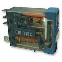
C10T13X24D
Description
RELAY, SPCO, 24VDC
Manufacturer
RELECO
Specifications of C10T13X24D
Coil Voltage Vdc Nom
24V
Contact Current Max
6A
Contact Voltage Ac Nom
250V
Contact Voltage Dc Max
24V
Coil Resistance
742ohm
Relay Mounting
Plug-In
External Width
12.5mm
External Depth
35.4mm
Svhc
No SVHC
Contact Configuration
SPCO
External Height
28.8mm
Rohs Compliant
Yes
Average Power Consumption
1.1VA
Lead Free Status / RoHS Status
Lead free / RoHS Compliant


power, available in both MR-C and QR-C
versions. Gold-flashed contacts 0,2µ or
plated 10µ Au (optional).
Operational voltage range:
Protection against transients
When the coil is disconnected from an
electromagnet, peaks of inverse voltage
appear at the terminals which can reach
very high values. These pulses can be
transmitted down the line associated
with the coil and could possibly affect
other components.
In the case of a relay being operated by
such devices as transistors, triacs, etc; it
may be necessary to protect against
transients.
Transients carried in the line
High voltage pulses can be carried in the
supply line to the relay coil. These may
appear in the form of peaks or bursts and
are generated by the connection and
disconnection
transformers, capacitors etc.
Normally a relay is unaffected by these
pulses, but if a diode is connected in
association with the coil, it must be cap-
able of withstanding an inverse voltage
higher than those of the incoming peaks.
Protection circuits
A protection circuit must efficiently cope
with pulses generated by the coil as well
as incoming line pulses.
EN61000 norms set levels of protection
for each application.
Releco relays are available with integrat-
ed protection circuits or with modules
plugged into sockets S3-MP or S3-MS.
Vdc
Coils
110
N
S
E
12
24
48
60
6
S relays: 0,8 ... 2,5 Un
E relays: 0,8 ... 1,7 Un
N relays: 0,8 ... 1,4 Un
DC relays adjusted to work at lower
Relays S
2K3
144
576
9K2
Sensitive relays, 250 mW
One change-over contact
Sensitive relays, 500 mW
Two change-over contacts
Sensitive relays, 800 mW
Three change-over contacts
Relays C3-S, C3-E, C3-N, C9-E
mA
42
21
10
5
of
Relays E
1K1
4K6
7K2
288
72
electric
83
42
21
10
mA
8,3
2K8
4K5
15K
Relays N
180
720
45
motors,
133
mA
66
33
17
13
7
in parallel but are physically displaced so
that the tungsten contact makes and
breaks the load. The silver contact is
used for carrying the stable current.
This relay was designed to switch
incandescent and fluorescent lamps, (with
p.f corrected), and DC inductive loads.
Only available in C7 type housing.
Maximum loads:
See table of electrical life on page 52.
X
For DC and AC relays up to 250V
Level II (1000V) up to 24V
Level III (2000V) from 25 to 60V
Level IV (4000V) from 61 to 250V
Note: LED connected in series with the
coil @ 220Vdc in QRC types.
D
DX Free wheeling diode + LED
Dampens transients caused by the relay
coil on de-energisation.
Levell III (2000V) up to 60 Vdc
Level IV (4000V) from 61 to 250 Vdc (*)
F
FX Polarity + free wheeling diode + LED
A diode in series with the coil protects
the relay from reverse connection.
Level II (1000V) up to 60 Vdc
Level IV (4000V) from 61 to 250 Vdc (*)
B
BX Bridge rectifier + LED indication
Allows the relay to operate in both AC or
DC without any polarity inconvenience.
Available only in voltages up to 60V
Protection level II (1000V)
R
RX Resistor and capacitor + LED
Suppressor for AC coils. Level III (2000V)
Available only in MRC
(*) Level III (2000V) in QRC types.
10A @ 230V AC15; 1,5A @ 110V DC1
W
QR-C coils
GENERAL INFORMATION
Vac
6A @ 230 AC5a/b (lamps)
115
230
24
48
Polarity and free wheeling diodes.
Free wheeling diode.
LED indication with rectifier.
Bridge rectifier incorporated.
Resistor and capacitor.
132
535
3K1 17
12K
High inrush current relay
Two open contacts, one of silver
nickel and one of tungsten work
83
42
mA
8,7
43
Vdc
110
types
12
24
48
Relays C7-W
443
1K8
110 110
9K
mA
12
54
27
Specifications
The data referred to in the specificat-
ions for each model refers to typical
values of “new” relays at 20° C.
Tables
The tables of electrical life and the
tables of maximum DC current show
the typical result of exhaustive tests
performed at an ambient temperature
of 20° C, operating frequency of 1200
operations / hour, and under perm-
anent connection.
The switching current ratings specified
in the catalogue refer to a minimum
electrical life of 100.000 operations.
Margin of over-voltage
A maximum over-voltage of 110% U
is permissible at the coil, with rated
current through the contacts at an
ambient temperature of 60° C.
Custom relays
Relays with special specifications can
be supplied after consultation with an
official Releco distributor.
A2
A1
A1
A2
A2
A1
A1
+
–
+
–
X
A1
A2
B
D
F
R
A2
A1
A2
A1
A2
A2
A1
A1
+
–
+
–
FX
BX
RX
DX
RELAYS
A2
n
Related parts for C10T13X24D
Image
Part Number
Description
Manufacturer
Datasheet
Request
R

Part Number:
Description:
RELAY, SPCO, 24VAC/DC
Manufacturer:
RELECO
Datasheet:
Part Number:
Description:
RELAY, SPCO, 230VAC
Manufacturer:
RELECO
Datasheet:

Part Number:
Description:
RELAY, DPCO, 24VAC/DC
Manufacturer:
RELECO
Datasheet:
Part Number:
Description:
RELAY, DPCO, 12VDC
Manufacturer:
RELECO
Datasheet:
Part Number:
Description:
RELAY, DPCO, 230VAC
Manufacturer:
RELECO
Datasheet:
Part Number:
Description:
RELAY, DPCO, 24VDC
Manufacturer:
RELECO
Datasheet:

Part Number:
Description:
POWER RELAY, SPCO, 24VDC, 10A, PLUG IN
Manufacturer:
RELECO
Datasheet:

Part Number:
Description:
POWER RELAY, DPCO, 115VAC, 10A, PLUG IN
Manufacturer:
RELECO
Datasheet:
Part Number:
Description:
POWER RELAY, DPCO, 24VDC, 10A, PLUG IN
Manufacturer:
RELECO
Datasheet:

Part Number:
Description:
POWER RELAY, 3PCO, 115VAC, 10A, PLUG IN
Manufacturer:
RELECO
Datasheet:

Part Number:
Description:
Power Inductors
Manufacturer:
Mitsumi Electronics
Datasheet:
Part Number:
Description:
Power Inductors
Manufacturer:
Mitsumi Electronics
Datasheet:
Part Number:
Description:
Power Inductors
Manufacturer:
Mitsumi Electronics
Datasheet:

Part Number:
Description:
Power Inductors
Manufacturer:
Mitsumi Electronics, Corp.
Datasheet: