8903LO30V01 SQUARE D, 8903LO30V01 Datasheet - Page 8
8903LO30V01
Manufacturer Part Number
8903LO30V01
Description
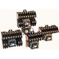
Lighting Contactor
Manufacturer
SQUARE D
Datasheet
1.8903LG20V01.pdf
(20 pages)
Specifications of 8903LO30V01
Contact Configuration
3NO
Relay Mounting
SMD
Coil Voltage Vac Nom
24V
Contact Current Max
30A
External Height
127mm
Continuous Load Current
30A
Peak Reflow Compatible (260 C)
No
External Width
73mm
Operating Voltage
600VAC
Load Current Inductive
30A
Load Current Resistive
30A
No. Of Poles
3
Rohs Compliant
No
Lead Free Status / RoHS Status
Contains lead / RoHS non-compliant


Class 8903 – Modifications (Forms)
8
“On-off” (momentary contact) push button
“On-off” push button (with holding circuit interlock)
“HAND-OFF-AUTO” selector switch. For key operator, add
Form C33, i.e. CC33
“On-off” selector switch. For key operator, add Form C33, i.e.
C6C33
Control circuit fuse (1 fuse)
Control circuit fuses (2 fuses)
Control circuit transformer standard capacity 50/60 Hz
Noise reduced enclosure and shock mounted panel
Addition of photoelectric receptacle
Addition of photoelectric receptacle with photo-cell
Addition of photoelectric receptacle and relay (R6)
Addition of terminal blocks (other than standard).
“xx” Represents the number of terminals needed.
Bracketing for internally mounted pilot device
Addition of 24 hour time clock (120-277v only)
Addition of 24 hour time clock w/day omission (120-277v)
Addition of 7 day time clock (120-277v)
Addition of 8865 TC12 lighting controller to lighting contactors
of any size. REQUIRES A 24V 60 Hz CONTROL CIRCUIT.
Addition of 24 hour time clock (120-277v only)
Addition of 24 hr time clock w/skip day (120-277v)
Addition of 7 day time clock (120-277v)
Addition of solid neutral terminal block
Red Pilot Light
Two or more lights
Red Push To Test Pilot Light
Two Wire Interface for Mechanically held
Three wire control for long distance applications.
Auxiliary contacts (specify number of N.O. + N.C.)
Addition of DC coil to Type L (7 poles max)
Auxiliary electrical interlock installed on disconnect switch or
circuit breaker operating mechanism
Coil Transient suppressor (120Vac Only)
Coil Transient suppressor (120Vac Only)
Addition of lightning arrestor
Substitute copper only lugs for standard
Substitute Anderson VC crimp style lugs for standard – per lug
adder – specify lug
Addition of under and overvoltage relay
Multiple contactors in common enclosure “xx” = number of
contactors needed
t Available.
Primary (Fuses) Secondary
With photo-cell installed
(PER TERMINAL PRICE)
(PER TERMINAL PRICE)
Interlock necessary for pilot light
one needed for each additional pilot light
Limited to 16 contactors thru 60 Amps, 4 contactors thru 200 Amps.
NIGHT-MASTER maximum 200 Amps, minimum 30 Amps.
DO NOT use Form X for any interlock which is wired in series with pilot light,
but DO specify how pilot light and interlock are to be wired into the circuit.
Not required on 400 A through 800 A electrically held versions only, which
have a control circuit requiring a 120V secondary; therefore, a transformer is
supplied. The transformer comes wired to L1 and L2 unless Form “S” is
called for. It is supplied with two primary and one secondary fuse.
Single primary voltage must be specified using the codes shown below:
2 100
2 100
2 100 VA Add. Cap. 1
2 200 VA Add. Cap. 1
2 300 VA Add. Cap. 1
VA Add.
VA Add.
Voltage 60 Hz
208-120
240-120
277-120
480-120
480-240
600-120
120-24
240-24
480-24
Cap. 0 ,
Cap. 1 ,
(each)
Description
for 200 and 300 A
for 100, 200 and 300 A
for 30 to 300 A
WIRED
UNWIRED
for 300 A
for 300 A
© 1998 Square D All Rights Reserved
Code
V89
V84
V82
V80
V85
V83
V81
V87
V86
G101R6
FF4T11
FF4T12
FF4T13
G10R6
Y10XX
G50xx
Y1532
Y1574
Letter
G101
K141
K141
Form
FF4T
K142
K143
K142
Y145
Y145
Y157
Y449
A12
G10
G53
K14
K14
R62
Y48
F4T
P21
X
Y74
G4
R6
A3
A3
C6
C6
F4
P1
C
C
N
F
P
,
1, 3R, 12
1, 3R, 12
3R, 4, 12
3R, 4, 12
3R, 4, 12
3R, 4, 12
1, 4, 12
1, 4, 12
1, 4, 12
1, 4, 12
1, 4, 12
1, 4, 12
Order Example
You have previously selected a Class 8903SMG2V02. V02
means that you need a coil voltage of 120-60/110-50 wired
for separate control. You would like to add form FF4T with
the transformer voltages being 480 volt primary, 120 volt
secondary.
The new and complete Class, Type, Voltage Code and
Form number:
Class
8903
NEMA
Enclo-
f Form numbers should always be shown in alphabetical order.
1, 12
1, 12
Type
sure
Any
Any
Any
Any
Any
Any
Any
Any
Any
Any
Any
Any
Any
Any
Any
Any
Any
Any
Any
Any
Any
Any
Any
Any
Any
3R
3R
3R
For electrically-held enclosed devices, the first pilot is wired in parallel with
the coil. Operating interlocks are required for all additional pilot lights.
Mechanically held devices require operating interlocks for all pilot lights.
Electrically held 20 Amp multipole contactors cannot add interlocks. Addi-
tional poles can be used for the same function, however. Mechanically held
(Type LX) provide one double throw auxiliary (or status) contact as standard.
1
1
1
Elec.
Held
t
t
t
t
t
t
t
t
t
t
t
t
t
t
t
t
t
t
t
t
t
t
t
t
t
t
t
t
t
t
t
t
t
t
SMG2
Type
Std.
Mech.
Held
t
t
t
t
t
t
t
t
t
t
t
t
t
t
t
t
t
t
t
t
t
t
t
t
t
t
t
t
t
t
t
t
t
t
t
t
t
VoltageCode
Used On
V81
Elec.
Held
t
t
t
t
t
t
t
t
t
t
t
t
t
t
t
t
t
t
t
t
t
t
t
t
t
t
t
t
t
t
t
t
Combo
Mech.
Held
t
t
t
t
t
t
t
t
t
t
t
t
t
t
t
t
t
t
t
t
t
t
t
t
t
t
t
t
t
t
t
t
t
t
t
t
Form
FF4T
1/98
MASTER
f
NIGHT-
Std.
t
t
t
t
t
t
t
t
t
t
t
t
t
t
t
t
t
t
t
t
t
t
t
t
t
t
t
t
t
®
Related parts for 8903LO30V01
Image
Part Number
Description
Manufacturer
Datasheet
Request
R

Part Number:
Description:
LED SPACER
Manufacturer:
Keystone Electronics
Datasheet:


Part Number:
Description:
Pushbutton, Non-Illum'd Red "STOP", Momentary, 1NO-1NC, Square 30mm, 10A, 600V
Manufacturer:
SQUARE D
Datasheet:

Part Number:
Description:
KITS,TWIDO? PROGRAMMABLE CONTROLLERS,KITS,TWIDOPACK STARTER KIT - ADVANCED LEVEL,PROGRAMMABLE CONTROLLERS,TWIDO? PROGRAMMABLE CONTROLLERS ,SQUARE D
Manufacturer:
SQUARE D

Part Number:
Description:
LAMPS,INDICATOR,STACKABLE,LAMPS, STACKABLE INDICATOR,VISUAL INDICATING SIGNALS,XVB SERIES INDICATING BANKS ,SQUARE D
Manufacturer:
SQUARE D
Part Number:
Description:
LAMPS,INDICATOR,STACKABLE,LAMPS, STACKABLE INDICATOR,VISUAL INDICATING SIGNALS,XVB SERIES INDICATING BANKS ,SQUARE D
Manufacturer:
SQUARE D
Datasheet:
Part Number:
Description:
CB ACCESSORY, UNDERVOLTAGE TRIP 48V DC
Manufacturer:
SQUARE D
Datasheet: