CA3KN40BD TELEMECANIQUE, CA3KN40BD Datasheet - Page 2
CA3KN40BD
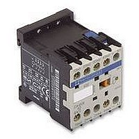
Manufacturer Part Number
CA3KN40BD
Description
Control Contactor
Manufacturer
TELEMECANIQUE
Datasheet
1.CA3KN40BD.pdf
(8 pages)
Specifications of CA3KN40BD
Contact Configuration
4NO
Relay Mounting
DIN Rail
Coil Voltage Vdc Nom
24V
Coil Power Vdc
1.5W
Length/height, External
58mm
Nom Operating Power
3W
External Width
45mm
External Depth
57mm
Operating Voltage
600VAC
Load Current Inductive
10A
Load Current Resistive
10A
No. Of Poles
4


Number of contacts
Rated operational voltage (Ue)
Rated insulation voltage (Ui)
Conventional thermal current (Ith)
Operational current frequency
Minimum switching capacity
Short-circuit protection
Rated making capacity
Overload current
Insulation resistance
Make before break distance
Operational power of contacts
Conforming to IEC/EN 60947-5-1
1 million operating cycles
3 million operating cycles
10 million operating cycles
Occasional making capacity
1
2
3
4
Contact characteristics of mini-control relays and instantaneous contact blocks
- 1 million operating cycles (
- 3 million operating cycles (
- 10 million operating cycles (
Electrical durability of contacts
for:
Thermal limit.
- maximum of 20 operating cycles
Breaking limit of contacts valid for:
- maximum of 50 operating cycles
Breaking limit of contacts valid for:
at 10 s intervals with current passing
for 0.5 s per operating cycle.
at 10 s intervals
(breaking current = making current
x cos ϕ 0.7).
Characteristics
References:
page 6/12
Schneider Electric
2a
2b
2c
),
),
).
Dimensions:
page 6/14
a.c. supply, category AC-15
Electrical durability (valid up to 3600 operating cycles per
hour) on an inductive load such as the coil of an
electromagnet: making current (cos ϕ 0.7) = 10 times
breaking current (cos ϕ 0.4).
Power broken in VA
16 000
10 000
On CAp-K
On LA1-K
Up to
Conforming to IEC/EN 60947-1, IEC/EN 60947-5-1
Conforming to VDE 0110 group C
Conforming to CSA C 22-2 n˚ 14
For ambient temperature ≤ 50 ˚C
U min (DIN 19 240)
I min
Conforming to IEC/EN 60947-1 & VDE 0660, gG fuse A
Conforming to IEC/EN 60947-1
Permissible for
CAp p p p -K and LA1-K: linked contacts
as per INRS, BIA and CNA specifications
V
VA
VA
VA
VA
8000
6000
5000
4000
3000
2000
1000
600
400
300
200
100
800
500
80
60
40
24
48
17
7
1000 2050 5000 10,000 14,000 13,000 9000
24
48
96
34
14
48
110/
127
240
86
36
2a
2b
1
4
220/
230
440
158
66
110
Control relays
K mini-control relays
Schemes:
page 6/15
120
2c
380/
400
800
288
120
1 s
500 ms
100 ms
I rms
220
440
880
317
132
380 500
440 690 V
600/
690
1200
500
200
V
V
V
V
A
Hz
V
mA
A
A
A
A
MΩ
mm
250
200
140
100
50
20
d.c. supply, category DC-13
Electrical durability (valid up to 1200 operating cycles
per hour) on an inductive load such as the coil of an
electromagnet, without economy resistor, the time
constant increasing with the load.
V
W
W
W
W
Power broken in W
4
2 or 4 for CA2-K and CA3-K: 2 for CA4-K
690
690
750
600
10
Up to 400
17
5
10
110
80
90
110
> 10
0.5 (see schemes, page 6/15 )
1000
100
700
500
300
200
80
60
50
40
30
20
10
24
120
55
15
720
8
6
12
48
80
38
11
600
24
110
60
30
9
400
48
4
3
2b
220
52
28
8
300
2a
2c
110
440
51
26
7
230
220
600
50
25
6
200
440 600 V
6/9
6.2
6
Related parts for CA3KN40BD
Image
Part Number
Description
Manufacturer
Datasheet
Request
R

Part Number:
Description:
Control Contactor
Manufacturer:
TELEMECANIQUE
Datasheet:

Part Number:
Description:
Contactor
Manufacturer:
TELEMECANIQUE
Datasheet:

Part Number:
Description:
Contactor
Manufacturer:
TELEMECANIQUE
Datasheet:
Part Number:
Description:
Control Contactor
Manufacturer:
TELEMECANIQUE
Datasheet:

Part Number:
Description:
CONTACTOR, 2NO/2NC, 9A, 230VAC
Manufacturer:
TELEMECANIQUE
Datasheet:

Part Number:
Description:
Contactor
Manufacturer:
TELEMECANIQUE
Datasheet:

Part Number:
Description:
CONTACTOR, 4KW, 400VAC
Manufacturer:
TELEMECANIQUE
Datasheet:

Part Number:
Description:
CONTACTOR, 5.5KW, 230VAC
Manufacturer:
TELEMECANIQUE
Datasheet:
Part Number:
Description:
CONTACTOR, 5.5KW, 400VAC
Manufacturer:
TELEMECANIQUE
Datasheet:

Part Number:
Description:
Contactor
Manufacturer:
TELEMECANIQUE
Datasheet:

Part Number:
Description:
PILOT LIGHT HEAD, WHITE
Manufacturer:
TELEMECANIQUE
Datasheet:

Part Number:
Description:
LENS HEAD, BA 9S
Manufacturer:
TELEMECANIQUE
Datasheet:
Part Number:
Description:
LENS HEAD, BA 9S
Manufacturer:
TELEMECANIQUE
Datasheet:

Part Number:
Description:
LED BODY, 24V
Manufacturer:
TELEMECANIQUE
Datasheet:
Part Number:
Description:
LED BODY, 48V
Manufacturer:
TELEMECANIQUE
Datasheet: