PIC18C601-I/L Microchip Technology, PIC18C601-I/L Datasheet
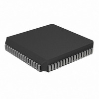
IC,MICROCONTROLLER,8-BIT,PIC CPU,CMOS,LDCC,68PIN,PLASTIC

PIC18C601-I/L

Manufacturer Part Number
PIC18C601-I/L
Description
IC,MICROCONTROLLER,8-BIT,PIC CPU,CMOS,LDCC,68PIN,PLASTIC
Manufacturer
Microchip Technology
Series
PIC® 18Cr

Specifications of PIC18C601-I/L

Rohs Compliant
YES
Core Processor
PIC
Core Size
8-Bit
Speed
25MHz
Connectivity
EBI/EMI, I²C, SPI, UART/USART
Peripherals
Brown-out Detect/Reset, LVD, POR, PWM, WDT
Number Of I /o
26
Program Memory Type
ROMless
Ram Size
1.5K x 8
Voltage - Supply (vcc/vdd)
4.2 V ~ 5.5 V
Data Converters
A/D 8x10b
Oscillator Type
External
Operating Temperature
-40°C ~ 85°C
Package / Case
68-PLCC
Processor Series
PIC18C
Core
PIC
Data Bus Width
8 bit
Data Ram Size
1.5 KB
Interface Type
3-Wire, I2C, SPI, USART
Maximum Clock Frequency
25 MHz
Number Of Programmable I/os
47
Number Of Timers
1 x 16 bit
Operating Supply Voltage
2 V to 5.5 V
Maximum Operating Temperature
+ 85 C
Mounting Style
SMD/SMT
3rd Party Development Tools
52715-96, 52716-328, 52717-734, 52712-325, EWPIC18
Development Tools By Supplier
DV164005, ICE4000, DV164136
Minimum Operating Temperature
- 40 C
On-chip Adc
10 bit
Lead Free Status / RoHS Status
Lead free / RoHS Compliant
For Use With
AC164309 - MODULE SKT FOR PM3 44PLCCXLT68L1 - SOCKET TRANSITION ICE 68PLCCAC174007 - MODULE SKT PROMATEII 68PLCC
Eeprom Size
-
Program Memory Size
-
Lead Free Status / Rohs Status
 Details
Other names
PIC18C601I/L

Available stocks

Company
Part Number
Manufacturer
Quantity
Price
Part Number:
PIC18C601-I/L
Manufacturer:
Microchip
Quantity:
229
Part Number:
PIC18C601-I/L
Manufacturer:
Microchip Technology
Quantity:
10 000
The PIC18C601/801 parts you have received conform
functionally to the Device Data Sheet (DS39541A),
except for the anomalies described below.
All the problems listed here will be addressed in future
revisions of the PIC18C601/801 silicon.
1. Module: WDT
2. Module: I/O
 2002 Microchip Technology Inc.
M
When the device is configured for either EC or RC
oscillator modes, with the Power-up Timer
enabled, bit TO of the RCON register (RCON<3>)
may default to ‘0’, even though no WDT time-out
has occurred.
The TO bit functions normally in all other configu-
rations.
Work around
1. Use bit TO in conjunction with bit POR
2. Use the latest silicon revision when it becomes
The four Least Significant bits of the data direction
registers TRISD, TRISE and TRISJ cannot be writ-
ten to while the EBDIS bit of the MEMCOM regis-
ter (MEMCOM<7>) is cleared. These bits remain
set (TRISn<7:0>=’1111’), and the corresponding
pins for their ports remain configured as inputs,
until the EBDIS bit is set (= ‘1’).
Work around
1. Write to the four Least Significant bits of
2. Use the latest silicon revision when it becomes
(RCON<1>) to determine if a RESET condi-
tion has occurred.
available.
TRISD, TRISE and TRISJ, only after setting
the EBDIS bit.
available.
PIC18C601/801 Rev. B1 Silicon/Data Sheet Errata
PIC18C601/801
3. Module: Core (DC Characteristics)
4. Module: Interrupts
Note:
The specification for the device Power-down
Current (parameter D020) has changed. The new
maximum value is 50 µA at 85°C.
This new value applies to both standard and
extended voltage range devices.
Work around
Use the latest silicon revision when it becomes
available.
High priority interrupts may become improperly
enabled, while low priority interrupts become
improperly disabled, at the same time. This may
occur when low priority interrupts are in an
enabled state and the following conditions occur
simultaneously:
Work around
1. Always disable low priority interrupts before
2. Use the latest silicon revision (C1 or higher)
Date Codes that pertain to this issue:
High priority interrupts are being changed
from an enabled to a disabled state; and
One or more low priority interrupts occur.
disabling high priority interrupts. Re-enable the
low priority interrupts afterwards, if necessary.
when it becomes available.
When the manufacture date of a newer
version of silicon is in production, the last
date where this issue may occur will be
specified.
ALL
DS80108B-page 1

Related parts for PIC18C601-I/L

PIC18C601-I/L Summary of contents

Page 1

... M PIC18C601/801 Rev. B1 Silicon/Data Sheet Errata The PIC18C601/801 parts you have received conform functionally to the Device Data Sheet (DS39541A), except for the anomalies described below. All the problems listed here will be addressed in future revisions of the PIC18C601/801 silicon. 1. Module: WDT When the device is configured for either oscillator modes, with the Power-up Timer enabled, bit TO of the RCON register (RCON< ...

Page 2

... PIC18C601/801 Clarifications/Corrections to the Data Sheet: In the Device Data Sheet (DS39541A), the following clarifications and corrections should be noted. 1. Module: Core (DC Characteristics) The specification for the device Supply Current (parameter D013 MHz, V OSC has changed. The new maximum value is 65 mA. This new value applies to both standard and extended voltage range devices ...

Page 3

... No D423 V Bandgap Reference Voltage Value BG  2002 Microchip Technology Inc. PIC18C601/801 Also, the minimum and maximum values for spec- ification D423 (bandgap voltage reference) have been added. These are shown in Table 2, below. The typical value for specification D423 remains unchanged. New Specification ...

Page 4

... Also, the title for Figure 22-1 of the Device Data Sheet is amended to read: “PIC18C601/801 (Industrial, Extended)”. This change also effects bits 3-0 in Register 18-1: LVDCON Register in the device data sheet. ...

Page 5

... Reserved on PIC18C601/801 0110 = 2.8V - Reserved on PIC18C601/801 0101 = 2.7V - Reserved on PIC18C601/801 0100 = 2.5V - Reserved on PIC18C601/801 0011 = Reserved on PIC18C601/801 and PIC18LC601/801 0010 = Reserved on PIC18C601/801 and PIC18LC601/801 0001 = Reserved on PIC18C601/801 and PIC18LC601/801 0000 = Reserved on PIC18C601/801 and PIC18LC801/601 LVDL3:LVDL0 modes which result in a trip point below the valid operating voltage of the device are not tested ...

Page 6

... PIC18C601/801 5. Module: USART The operation of the USART Transmit Interrupt flag bit TXIF (PIR1<4>) is clarified as follows: TXIF is not cleared immediately upon loading data into the transmit buffer TXREG. The flag bit becomes valid in the second instruction cycle fol- lowing the load instruction (see Example 1). Poll- ing TXIF immediately following a load of TXREG will give invalid results (Example 2) ...

Page 7

... Issues and 4 (WDT, I/O, Core and Interrupts modules). Under Clarifications/Corrections to the Data Sheet, added Core (DC Characteristics) issue (page 2, item 1). Rev B Document (2/2002) Under Clarifications/Corrections to the Data Sheet, added Interrupts, LVD, Core and USART issues (pages 2 through 5, items and 5).  2002 Microchip Technology Inc. PIC18C601/801 DS80108B-page 7 ...

Page 8

... PIC18C601/801 NOTES: DS80108B-page 8  2002 Microchip Technology Inc. ...

Page 9

... Serialized Quick Term Programming (SQTP service mark of Microchip Technology Incorporated in the U.S.A. All other trademarks mentioned herein are property of their respective companies. © 2002, Microchip Technology Incorporated, Printed in the U.S.A., All Rights Reserved. Printed on recycled paper. Microchip received QS-9000 quality system ...

Page 10

... Korea Microchip Technology Korea 168-1, Youngbo Bldg. 3 Floor Samsung-Dong, Kangnam-Ku Seoul, Korea 135-882 Tel: 82-2-554-7200 Fax: 82-2-558-5934 Singapore Microchip Technology Singapore Pte Ltd. 200 Middle Road #07-02 Prime Centre Singapore, 188980 Tel: 65-334-8870 Fax: 65-334-8850 Taiwan Microchip Technology Taiwan 11F-3, No. 207 ...

Related keywords