MCP1406-E/AT Microchip Technology, MCP1406-E/AT Datasheet
MCP1406-E/AT
Specifications of MCP1406-E/AT


Related parts for MCP1406-E/AT


MCP1406-E/AT Summary of contents
Page 1
... MOSFETs intended state will not be affected, even by large transients. The input to the MCP1406/07 may be driven directly from either TTL or CMOS (3V to 18V). These devices are highly latch-up resistant under any conditions within their power and voltage ratings ...
Page 2
... MCP1406/07 (1) Functional Block Diagram Input Effective Input GND Note 1: Unused inputs should be grounded. DS22019A-page 2 Inverting 130 µA 300 mV Non-inverting 4.7V MCP1406 Inverting MCP1407 Non-inverting V DD Output Output © 2006 Microchip Technology Inc. ...
Page 3
... V — 130 250 µA — 35 100 µA = +25°C A MCP1406/07 ≤ 18V. DD Conditions 0V ≤ V ≤ Test DC Test mA 18V OUT mA 18V OUT DD = 18V (Note Note 2, Note 3 Duty cycle ≤ 2%, t ≤ 300 µsec. Figure 4-1, Figure 4-2 ...
Page 4
... MCP1406/07 DC CHARACTERISTICS (OVER OPERATING TEMPERATURE RANGE) Electrical Specifications: Unless otherwise indicated, operating temperature range with 4.5V ≤ V Parameters Sym Input Logic ‘1’, High Input Voltage V IH Logic ‘0’, Low Input Voltage V IL Input Current I IN Input Voltage V IN Output ...
Page 5
... FIGURE 2-4: Voltage 15V 10000 100 FIGURE 2-5: Load RISE FIGURE 2-6: Supply Voltage. MCP1406/07 10,000 pF 8,200 pF 4,700 pF 1,000 pF 6,800 pF 2,500 Supply Voltage (V) Fall Time vs. Supply 5V 10V 15V 1000 10000 Capacitive Load (pF) Fall Time vs. Capacitive Supply Voltage (V) Propagation Delay vs. ...
Page 6
... MCP1406/07 Typical Performance Curves (Continued) Note: Unless otherwise indicated +25°C with 4.5V < 200 175 150 t 125 D1 100 Input Amplitude (V) FIGURE 2-7: Propagation Delay Time vs. Input Amplitude 18V -40 -25 - 110 125 o Temperature ( C) FIGURE 2-8: Propagation Delay Time vs. Temperature. 180 160 140 120 ...
Page 7
... FIGURE 2-17: Frequency MHz MHz 10000 10 FIGURE 2-18: Frequency. MCP1406/07 = 18V 10,000 pF 6,800 pF 1,000 pF 2,500 pF 4,700 pF 100 pF 100 1000 Frequency (kHz) Supply Current vs. = 12V 10,000 pF 6,800 pF 1,000 pF 4,700 pF 2,500 pF 100 pF 100 1000 Frequency (kHz) Supply Current vs 10,000 pF 6,800 pF 4,700 pF 1,000 pF ...
Page 8
... Output Resistance (Output High) vs. Supply Voltage (MCP1407 2.5V (MCP1406 +125 + Supply Voltage (V) FIGURE 2-20: Output Resistance (Output Low) vs. Supply Voltage. DS22019A-page 8 <= 18V 1.E- (MCP1406 1.E-08 -10 10 1.E- FIGURE 2-21: Supply Voltage Supply Voltage (V) Crossover Energy vs. © 2006 Microchip Technology Inc. ...
Page 9
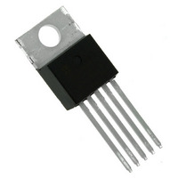
... TO-220 Metal Tab The metal tab on the TO-220 package potentail. This metal tab is not intended to be the V connection to MCP1406/07. V using the Supply Input pin of the TO-220. = 18V). The low MCP1406/07 Description DD ...
Page 10
... MOSFETs or IGBTs. In high frequency switching power supplies, the PWM controller may not have the drive capability to directly drive the power MOSFET. A MOSFET driver like the MCP1406/07 family can be used to provide additional drive current capability. 4.2 MOSFET Driver Timing ...
Page 11
... The MCP1406/07 devices have two pins each for V OUTPUT, and GND. Both pins must be used for proper operation. This also lowers path inductance which will, along with proper decoupling, help minimize ringing in the circuit. Placing a ground plane beneath the MCP1406/07 will ...
Page 12
... DS22019A-page 12 Example MCP1406 EAT 0644256 : Example MCP1406 E/MF 0644 256 Example: MCP1407 E/P^^256 e 3 0644 Example: MCP1406E SN^^0644 e 3 256 ) e 3 © 2006 Microchip Technology Inc. ...
Page 13
... P .146 .156 3.71 L .540 .560 13.72 J1 .090 .115 2.29 C1 .014 .022 0.36 β .025 .040 0.64 α 3° 7° 3° MCP1406/07 MAX 1.83 6.93 1.02 4.83 10.54 14.99 6.55 1.40 2.87 3.96 14.22 2.92 0.56 1.02 7° Revised 08-01-05 DS22019A-page 13 ...
Page 14
... MCP1406/07 8-Lead Plastic Dual Flat, No Lead Package (MF) - 6x5 mm Body [DFN-S] Note: For the most current package drawings, please see the Microchip Packaging Specification located at http://www.microchip.com/packaging D N NOTE TOP VIEW A3 Number of Pins Pitch Overall Height Standoff Contact Thickness Overall Length Overall Width ...
Page 15
... MCP1406/07 α MILLIMETERS NOM MAX 8 2.54 3.94 4.32 3.30 3.68 7.94 8.26 6.35 6.60 9.46 9.78 3.30 3.43 0.29 0.38 1.46 1.78 ...
Page 16
... MCP1406/07 8-Lead Plastic Small Outline (SN) – Narrow, 150 mil Body (SOIC) Note: For the most current package drawings, please see the Microchip Packaging Specification located at http://www.microchip.com/packaging 45° c β Units Dimension Limits n Number of Pins p Pitch Overall Height A Molded Package Thickness A2 Standoff § ...
Page 17
... APPENDIX A: REVISION HISTORY Revision A (December 2006) • Original Release of this Document. © 2006 Microchip Technology Inc. MCP1406/07 DS22019A-page 17 ...
Page 18
... MCP1406/07 NOTES: DS22019A-page 18 © 2006 Microchip Technology Inc. ...
Page 19
... MCP1406/07 . MCP1406-E/MF: 6A High-Speed MOSFET Driver, Inverting 8LD DFN package. MCP1406-E/AT: 6A High-Speed MOSFET Driver, Inverting 5LD TO-220 package . MCP1406-E/SN: 6A High-Speed MOSFET Driver, Inverting 8LD SOIC package . MCP1406-E/P: 6A High-Speed MOSFET Driver, Inverting 8LD PDIP package . MCP1406T-E/MF: Tape and Reel, 6A High-Speed MOSFET Driver, Inverting, 8LD DFN pkg ...
Page 20
... MCP1406/07 NOTES: DS22019A-page 20 © 2006 Microchip Technology Inc. ...
Page 21
... Select Mode, Smart Serial, SmartTel, Total Endurance, UNI/O, WiperLock and ZENA are trademarks of Microchip Technology Incorporated in the U.S.A. and other countries. SQTP is a service mark of Microchip Technology Incorporated in the U.S.A. All other trademarks mentioned herein are property of their respective companies. ...
Page 22
... Fax: 886-3-572-6459 Taiwan - Kaohsiung Tel: 886-7-536-4818 Fax: 886-7-536-4803 Taiwan - Taipei Tel: 886-2-2500-6610 Fax: 886-2-2508-0102 Thailand - Bangkok Tel: 66-2-694-1351 Fax: 66-2-694-1350 © 2006 Microchip Technology Inc. EUROPE Austria - Wels Tel: 43-7242-2244-39 Fax: 43-7242-2244-393 Denmark - Copenhagen Tel: 45-4450-2828 Fax: 45-4485-2829 France - Paris Tel: 33-1-69-53-63-20 ...