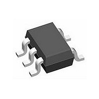
LMV7271MG National Semiconductor, LMV7271MG Datasheet - Page 14

LMV7271MG
Manufacturer Part Number
LMV7271MG
Description
IC,VOLT COMPARATOR,SINGLE,TSSOP,5PIN,PLASTIC
Manufacturer
National Semiconductor
Datasheet
1.LMV7271MG.pdf
(18 pages)
Specifications of LMV7271MG
Rohs Compliant
NO
Number Of Elements
1
Output Type
Push-Pull
Technology
BiCMOS
Input Offset Voltage
4mV
Input Bias Current (typ)
10nA
Single Supply Voltage (typ)
3/5V
Dual Supply Voltage (typ)
Not RequiredV
Supply Current (max)
0.014mA
Power Supply Requirement
Single
Common Mode Rejection Ratio
78dB
Power Supply Rejection Ratio
80dB
Single Supply Voltage (min)
1.8V
Single Supply Voltage (max)
5.5V
Dual Supply Voltage (min)
Not RequiredV
Dual Supply Voltage (max)
Not RequiredV
Operating Temp Range
-40C to 85C
Operating Temperature Classification
Industrial
Mounting
Surface Mount
Pin Count
5
Package Type
SC-70
Lead Free Status / Rohs Status
Not Compliant
Available stocks
Company
Part Number
Manufacturer
Quantity
Price
Part Number:
LMV7271MG
Manufacturer:
NS/国半
Quantity:
20 000
Company:
Part Number:
LMV7271MGX
Manufacturer:
NS
Quantity:
9 000
Company:
Part Number:
LMV7271MGX
Manufacturer:
FAIRCHILD
Quantity:
840
Part Number:
LMV7271MGX
Manufacturer:
NS/国半
Quantity:
20 000
Part Number:
LMV7271MGX/NOPB
Manufacturer:
TI/德州仪器
Quantity:
20 000
www.national.com
NEGATIVE PEAK DETECTOR
For the negative detector, the output transistor of the com-
parator acts as a low impedance current sink. Since there is
no pull-up resistor, the only discharge path will be the 1MΩ
resistor and any load impedance used. Decay time is
changed by varying the 1MΩ resistor.
SQUARE WAVE GENERATOR
A typical application for a comparator is as a square wave
oscillator. The circuit below generates a square wave whose
period is set by the RC time constant of the capacitor C
resistor R
signal propagation delay of the comparator, and by the ca-
pacitive loading at the output, which limits the output slew
rate.
4
. The maximum frequency is limited by the large
FIGURE 9. Negative Peak Detector
20064055
1
and
14
To analyze the circuit, consider it when the output is high. That
implies that the inverted input (V
verting input (V
R
inverting input. The value of V
If R
At this point the comparator switches pulling down the output
to the negative rail. The value of V
If R
The capacitor C
V
parator switches again, bringing it back to the initial stage. The
time period is equal to twice the time it takes to discharge
C
the formula for the frequency is:
F = 1/(2·R
C
4,
1
from 2V
1
1
decreases till it is equal to V
and the voltage V
= R
= R
2
2
= R
= R
4
·C
CC
FIGURE 10. Squarewave Oscillator
1
/3 to V
3
3
·ln2)
, then V
, then V
A
1
). This causes the C
now discharges through R
CC
C
A1
A2
/3, which is given by R
increases till it is equal to the non-
= 2V
= V
CC
CC
A
/3
at this point is
/3
A2
C
) is lower than the non-in-
A
, at which point the com-
1
at this point is
to get charged through
4
, and the voltage
4
C
20064056
1
.ln2. Hence
20064057


