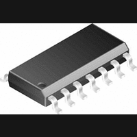
LMC6034IM National Semiconductor, LMC6034IM Datasheet

LMC6034IM
Specifications of LMC6034IM
Available stocks
Related parts for LMC6034IM
LMC6034IM Summary of contents
Page 1
... Temperature Range Industrial −40˚C T +85˚C J LMC6034IN LMC6034IM © 1999 National Semiconductor Corporation DS011134 n Low offset voltage drift: 2.3 µV/˚C n Ultra low input bias current Input common-mode range includes V n Operating Range from +5V to +15V supply = 400 µA/amplifier; independent of V ...
Page 2
... Absolute Maximum Ratings If Military/Aerospace specified devices are required, please contact the National Semiconductor Sales Office/ Distributors for availability and specifications. Differential Input Voltage + − Supply Voltage (V − Output Short Circuit to V − Output Short Circuit to V Lead Temperature (Soldering, 10 sec.) Storage Temperature Range ...
Page 3
DC Electrical Characteristics Unless otherwise specified, all limits guaranteed for T − = GND = 0V 1.5V 2.5V, and OUT Symbol Parameter V Output Voltage Swing O I Output Current O I Supply ...
Page 4
AC Electrical Characteristics Unless otherwise specified, all limits guaranteed for T − = GND = 0V 1.5V 2.5V, and OUT Symbol Parameter SR Slew Rate GBW Gain-Bandwidth Product Phase Margin M G Gain ...
Page 5
Typical Performance Characteristics Output Characteristics Current Sourcing DS011134-27 Open-Loop Frequency Response DS011134-30 Stability vs Capacitive Load DS011134-33 Note: Avoid resistive loads of less than 500 , as they may cause instability. Applications Hint Amplifier Topolgy The topology chosen for the ...
Page 6
Applications Hint (Continued) FIGURE 1. LMC6034 Circuit Topology (Each Amplifier) The large signal voltage gain while sourcing is comparable to traditional bipolar op amps, even with a 600 gain while sinking is higher than most CMOS op amps, due to ...
Page 7
Applications Hint (Continued) pacitance tolerate additional phase shifts in the loop, or excessive capacitive load decrease the noise or band- width, or simply because the particular circuit implementa- tion needs more feedback capacitance to be sufficiently ...
Page 8
Applications Hint (Continued) FIGURE 6. Guard Ring Connections Inverting Amplifier FIGURE 7. Guard Ring Connections Non-Inverting Amplifier FIGURE 8. Guard Ring Connections Follower FIGURE 9. Guard Ring Connections Howland Current Pump The designer should be aware that when it is ...
Page 9
Typical Single-Supply Applications Additional single-supply applications ideas can be found in the LM324 datasheet. The LMC6034 is pin-for-pin compat- ible with the LM324 and offers greater bandwidth and input resistance over the LM324. These features will improve the performance of ...
Page 10
Typical Single-Supply Applications = 5.0 VDC) (Continued Bandpass Filter = 2.1 Gain = −8 High-Pass Filter = 0.895 Gain = 1 2 ...
Page 11
... Physical Dimensions inches (millimeters) unless otherwise noted Small Outline Dual-In-Line Pkg. (M) Order Number LMC6034IM NS Package Number M14A Molded Dual-In-Line Pkg. (N) Order Number LMC6034IN NS Package Number N14A 11 www.national.com ...
Page 12
... National Semiconductor Asia Pacific Customer Fax: +49 (0) 1 80-530 85 86 Response Group Email: europe.support@nsc.com Tel: 65-2544466 Fax: 65-2504466 Tel: +49 (0) 1 80-532 78 32 Email: sea.support@nsc.com Tel: +49 (0) 1 80-534 16 80 National Semiconductor Japan Ltd. Tel: 81-3-5639-7560 Fax: 81-3-5639-7507 ...


