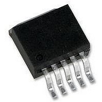
LM2585S-ADJ National Semiconductor, LM2585S-ADJ Datasheet - Page 4

LM2585S-ADJ
Manufacturer Part Number
LM2585S-ADJ
Description
DC/DC Converter IC
Manufacturer
National Semiconductor
Specifications of LM2585S-ADJ
Input Voltage
40V
Output Voltage
37V
No. Of Pins
5
Termination Type
SMD
Mounting Type
Through Hole
Output Current Max
0.5A
Peak Reflow Compatible (260 C)
No
Supply Voltage Max
40V
Lead Free Status / RoHS Status
Contains lead / RoHS non-compliant
Available stocks
Company
Part Number
Manufacturer
Quantity
Price
Company:
Part Number:
LM2585S-ADJ
Manufacturer:
NS
Quantity:
9 282
Company:
Part Number:
LM2585S-ADJ
Manufacturer:
NSC
Quantity:
5 510
Company:
Part Number:
LM2585S-ADJ/NOPB
Manufacturer:
TI
Quantity:
15 000
www.national.com
COMMON DEVICE PARAMETERS for all versions (Note 5)
I
V
f
f
V
I
I
D
I
V
V
I
Symbol
S
O
SC
EAO
SS
L
CL
Electrical Characteristics (All Versions)
JA
JA
JC
JA
JA
JA
JC
Note 1: Absolute Maximum Ratings indicate limits beyond which damage to the device may occur. Operating ratings indicate conditions the device is intended to
be functional, but device parameter specifications may not be guaranteed under these conditions. For guaranteed specifications and test conditions, see the Electrical
Characteristics.
Note 2: Note that switch current and output current are not identical in a step-up regulator. Output current cannot be internally limited when the LM2585 is used as
a step-up regulator. To prevent damage to the switch, the output current must be externally limited to 3A. However, output current is internally limited when the
LM2585 is used as a flyback regulator (see the Application Hints section for more information).
UV
EAO
SUS
SAT
Input Supply
Current
Input Supply
Undervoltage
Lockout
Oscillator Frequency
Short-Circuit
Frequency
Error Amplifier
Output Swing
Error Amp
Output Current
(Source or Sink)
Soft Start Current
Maximum Duty
Cycle
Switch Leakage
Current
Switch Sustaining
Voltage
Switch Saturation
Voltage
NPN Switch
Current Limit
Thermal Resistance
Parameters
(Switch Off)
(Note 8)
I
R
Measured at Switch Pin
R
V
Measured at Switch Pin
R
V
Upper Limit
(Note 7)
Lower Limit
(Note 8)
(Note 9)
V
V
R
(Note 7)
Switch Off
V
dV/dT = 1.5V/ns
I
T Package, Junction to
Ambient (Note 10)
T Package, Junction to
Ambient (Note 11)
T Package, Junction to
Case
S Package, Junction to
Ambient (Note 12)
S Package, Junction to
Ambient (Note 13)
S Package, Junction to
Ambient (Note 14)
S Package, Junction to
Case
SWITCH
SWITCH
COMP
FEEDBACK
FEEDBACK
COMP
SWITCH
LOAD
LOAD
LOAD
LOAD
= 100
= 100
= 100
= 100
= 1.0V
= 1.0V
Conditions
= 1.8A
= 3.0A
= 60V
= 1.15V
= 0.92V
4
Typical
3.30
0.25
11.0
0.45
100
165
2.8
4.0
11
50
25
98
15
65
45
56
35
26
2
2
2.6/2.4
110/70
8.0/7.0
85/75
93/90
3.05
Min
3.0
65
15.5/16.5
0.40/0.55
17.0/19.0
100/115
115/125
260/320
300/600
0.65/0.9
Max
3.75
7.0
Units
˚C/W
kHz
kHz
mA
mA
µA
µA
µA
%
V
V
V
V
V
A


