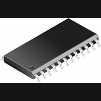
LM2575HVS-5.0 National Semiconductor, LM2575HVS-5.0 Datasheet - Page 13

LM2575HVS-5.0
Manufacturer Part Number
LM2575HVS-5.0
Description
DC/DC Converter IC
Manufacturer
National Semiconductor
Specifications of LM2575HVS-5.0
Input Voltage
60V
Output Current
1A
Output Voltage
5V
No. Of Pins
24
Mounting Type
Surface Mount
Peak Reflow Compatible (260 C)
No
Supply Voltage Max
60V
Leaded Process Compatible
No
Lead Free Status / RoHS Status
Contains lead / RoHS non-compliant
Available stocks
Company
Part Number
Manufacturer
Quantity
Price
Part Number:
LM2575HVS-5.0
Manufacturer:
NS/国半
Quantity:
20 000
Company:
Part Number:
LM2575HVS-5.0/NOPB
Manufacturer:
National Semiconductor
Quantity:
1 978
Given:
V
V
I
F = Switching Frequency (Fixed at 52 kHz)
1. Programming Output Voltage (Selecting R1 and R2, as
shown in Figure 2 )
Use the following formula to select the appropriate resistor
values.
R
cient and stability with time, use 1% metal film resistors)
2. Inductor Selection (L1)
A. Calculate the inductor Volt • microsecond constant,
E • T (V • µs), from the following formula:
B. Use the E • T value from the previous formula and match
it with the E • T number on the vertical axis of the Inductor
Value Selection Guide shown in Figure 7 .
C. On the horizontal axis, select the maximum load current.
D. Identify the inductance region intersected by the E • T
value and the maximum load current value, and note the in-
ductor code for that region.
E. Identify the inductor value from the inductor code, and se-
lect an appropriate inductor from the table shown in Figure 9 .
Part numbers are listed for three inductor manufacturers.
The inductor chosen must be rated for operation at the
LM2575 switching frequency (52 kHz) and for a current rat-
ing of 1.15 x I
the inductor section in the application hints section of this
data sheet.
LOAD
(Continued)
OUT
IN
1
PROCEDURE (Adjustable Output Voltage Versions)
(Max) = Maximum Input Voltage
can be between 1k and 5k. (For best temperature coeffi-
(Max) = Maximum Load Current
= Regulated Output Voltage
LOAD
. For additional inductor information, see
13
Given:
V
V
I
F = 52 kHz
1.Programming Output Voltage (Selecting R1 and R2)
R2 = 1k (8.13 − 1) = 7.13k, closest 1% value is 7.15k
2. Inductor Selection (L1)
A. Calculate E • T (V • µs)
B. E • T = 115 V • µs
C. I
D. Inductance Region = H470
E. Inductor Value = 470 µH Choose from AIE part
# 430-0634, Pulse Engineering part # PE-53118, or Renco
part # RL-1961.
LOAD
OUT
IN
(Max) = 25V
LOAD
EXAMPLE (Adjustable Output Voltage Versions)
(Max) = 1A
= 10V
(Max) = 1A
www.national.com


