KBU6G/51 Vishay, KBU6G/51 Datasheet - Page 3
KBU6G/51
Manufacturer Part Number
KBU6G/51
Description
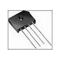
6A,400V,IN-LINE BRIDGE RECT.
Manufacturer
Vishay
Datasheet
1.KBU6G51.pdf
(4 pages)
Specifications of KBU6G/51
Rohs Compliant
NO
Phase Type
Single Phase
Number Of Elements
1
Peak Rep Rev Volt
400V
Rms Voltage (max)
280V
Peak Non-repetitive Surge Current (max)
250A
Avg. Forward Curr (max)
6A
Rev Curr
5uA
Forward Voltage
1V
Package Type
Case KBU
Operating Temp Range
-50C to 150C
Pin Count
4
Mounting
Through Hole
Operating Temperature Classification
Automotive
Lead Free Status / Rohs Status
Not Compliant


PACKAGE OUTLINE DIMENSIONS in inches (millimeters)
Document Number: 88657
Revision: 15-Apr-08
Figure 3. Typical Instantaneous Forward Characteristics Per Diode
Figure 4. Typical Reverse Leakage Characteristics Per Diode
0.01
100
100
0.1
0.1
10
10
1
1
0.6
0
Percent of Rated Peak Reverse Voltage (%)
0.7
Instantaneous Forward Voltage (V)
20
0.8
40
0.9
PDD-Americas@vishay.com, PDD-Asia@vishay.com, PDD-Europe@vishay.com
For technical questions within your region, please contact one of the following:
T
Pulse Width = 300 µs
1 % Duty Cycle
J
T
T
= 25 °C
1.0
J
J
60
= 25 °C
= 100 °C
1.1
(19.3)
(25.4)
0.760
MAX.
MIN.
1.0
0.205 (5.2)
0.185 (4.7)
80
0.160 (4.1)
0.140 (3.6)
1.2
0.220 (5.6)
0.180 (4.6)
0.660
(16.8)
0.700
(17.8)
100
1.3
0.075 (1.9) R TYP. (2 Places)
Case Style KBU
0.895 (22.7)
0.935 (23.7)
0.240 (6.09)
0.200 (5.08)
1000
100
10
0.052 (1.3)
0.048 (1.2)
Figure 5. Typical Junction Capacitance Per Diode
0.455 (11.3)
0.405 (10.3)
0.165 (4.2)
0.185 (4.7)
1
DIA.
45°
Vishay General Semiconductor
0.280 (7.1)
0.260 (6.6)
0.085 (2.2)
0.065 (1.7)
KBU6A thru KBU6M
Reverse Voltage (V)
10
T
f = 1.0 MHz
V
J
sig
= 25 °C
= 50 mVp-p
www.vishay.com
100
3
Related parts for KBU6G/51
Image
Part Number
Description
Manufacturer
Datasheet
Request
R

Part Number:
Description:
RECTIFIER BRIDGE 6A 400V KBU
Manufacturer:
Vishay
Datasheet:

Part Number:
Description:
DIODE 6A 400V KBU
Manufacturer:
Vishay
Datasheet:

Part Number:
Description:
357-036-542-201 CARDEDGE 36POS DL .156 BLK LOPRO
Manufacturer:
Vishay
Datasheet:
Part Number:
Description:
357-036-542-201 CARDEDGE 36POS DL .156 BLK LOPRO
Manufacturer:
Vishay
Datasheet:
Part Number:
Description:
357-036-542-201 CARDEDGE 36POS DL .156 BLK LOPRO
Manufacturer:
Vishay
Datasheet:
Part Number:
Description:
357-036-542-201 CARDEDGE 36POS DL .156 BLK LOPRO
Manufacturer:
Vishay
Datasheet:
Part Number:
Description:
357-036-542-201 CARDEDGE 36POS DL .156 BLK LOPRO
Manufacturer:
Vishay
Datasheet:
Part Number:
Description:
357-036-542-201 CARDEDGE 36POS DL .156 BLK LOPRO
Manufacturer:
Vishay
Datasheet:
Part Number:
Description:
357-036-542-201 CARDEDGE 36POS DL .156 BLK LOPRO
Manufacturer:
Vishay
Datasheet:
Part Number:
Description:
357-036-542-201 CARDEDGE 36POS DL .156 BLK LOPRO
Manufacturer:
Vishay
Datasheet:
Part Number:
Description:
357-036-542-201 CARDEDGE 36POS DL .156 BLK LOPRO
Manufacturer:
Vishay
Datasheet:
Part Number:
Description:
357-036-542-201 CARDEDGE 36POS DL .156 BLK LOPRO
Manufacturer:
Vishay
Datasheet:
Part Number:
Description:
357-036-542-201 CARDEDGE 36POS DL .156 BLK LOPRO
Manufacturer:
Vishay
Datasheet:
Part Number:
Description:
357-036-542-201 CARDEDGE 36POS DL .156 BLK LOPRO
Manufacturer:
Vishay
Datasheet:
Part Number:
Description:
357-036-542-201 CARDEDGE 36POS DL .156 BLK LOPRO
Manufacturer:
Vishay
Datasheet: