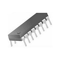
DS26C31TN National Semiconductor, DS26C31TN Datasheet - Page 4

DS26C31TN
Manufacturer Part Number
DS26C31TN
Description
RS422/485 Line Driver IC
Manufacturer
National Semiconductor
Datasheet
1.DS26C31TN.pdf
(13 pages)
Specifications of DS26C31TN
Device Type
Line
Driver Case Style
DIP
No. Of Pins
16
Operating Temperature Range
-40°C To +85°C
Termination Type
Through Hole
Mounting Type
Through Hole
Supply Voltage Min
4.5V
Interface Circuit Standard 1
EIA-422/RS-422
Number Of Receivers
Not Required
Number Of Transmitters
4
Number Of Transceivers
Not Required
Data Transmission Topology
Multidrop
Receiver Signal Type
Not Required
Transmitter Signal Type
Differential
Single Supply Voltage (typ)
5V
Single Supply Voltage (min)
4.5V
Single Supply Voltage (max)
5.5V
Dual Supply Voltage (typ)
Not RequiredV
Dual Supply Voltage (min)
Not RequiredV
Dual Supply Voltage (max)
Not RequiredV
Power Supply Requirement
Single
Operating Temp Range
-40C to 85C
Operating Temperature Classification
Industrial
Mounting
Through Hole
Pin Count
16
Package Type
PDIP
Lead Free Status / RoHS Status
Contains lead / RoHS non-compliant
Lead Free Status / RoHS Status
Contains lead / RoHS non-compliant
Available stocks
Company
Part Number
Manufacturer
Quantity
Price
Part Number:
DS26C31TN
Manufacturer:
NS/国半
Quantity:
20 000
Company:
Part Number:
DS26C31TN/NOPB
Manufacturer:
NSC
Quantity:
318
Part Number:
DS26C31TN/NOPB
Manufacturer:
NS/国半
Quantity:
20 000
www.national.com
t
t
t
PHZ
PZL
PZH
Comparison Table of Switching Characteristics into “LS-Type”
Load
V
Note 12: This table is provided for comparison purposes only. The values in this table for the DS26C31 reflect the performance of the device but are not tested or
guaranteed.
Note 13: ESD Rating:
Logic Diagram
AC Test Circuit and Switching
Time Waveforms
Note: C1 = C2 = C3 = 40 pF (Including Probe and Jig Capacitance), R1 = R2 = 50Ω, R3 = 500Ω.
CC
Symbol
= 5V, T
HBM (1.5 kΩ, 100 pF)
Inputs ≥ 1500V
Outputs ≥ 1000V
EIAJ (0Ω, 200 pF) ≥ 350V
(Continued)
A
= 25˚C, t
Output Disable Time
(Note 10)
Output Enable Time
Output Enable Time
r
≤ 6 ns, t
Parameter
f
≤ 6 ns (Figures 2, 4, 5, 6) (Note 12)
FIGURE 1. AC Test Circuit
C
S1 Open
S2 Closed
C
S1 Closed
S2 Open
C
S1 Open
S2 Closed
L
L
L
Conditions
= 10 pF
= 30 pF
= 30 pF
4
Typ
14
11
4
DS26C31T
Max
20
17
7
00857403
Typ
15
20
20
DS26LS31C
00857402
Max
25
30
30
Units
ns
ns
ns


