CDB5343 Cirrus Logic Inc, CDB5343 Datasheet
CDB5343
Specifications of CDB5343


Related parts for CDB5343


CDB5343 Summary of contents
Page 1
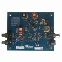
... The CS5343/4 is available in a 10-pin TSSOP package for both Commercial (-40° to +85° C) and Automotive grades (-40° to +105° C). The CDB5343 Customer Demonstration Board is also available for device evalu- ation and implementation suggestions. Please refer to the “Ordering Information” on page 20 details ...
Page 2
TABLE OF CONTENTS 1. PIN DESCRIPTIONS .............................................................................................................................. 4 2. CHARACTERISTICS AND SPECIFICATIONS ...................................................................................... 5 RECOMMENDED OPERATING CONDITIONS ..................................................................................... 5 ABSOLUTE MAXIMUM RATINGS ......................................................................................................... 5 ANALOG CHARACTERISTICS - COMMERCIAL GRADE (-CZZ) ......................................................... 6 ANALOG CHARACTERISTICS - AUTOMOTIVE GRADE (-DZZ) ......................................................... 7 ...
Page 3
LIST OF TABLES Table 1. Master/Slave Mode Selection ...................................................................................................... 13 Table 2. Speed Modes and the Associated Sample Rates (Fs) in Slave Mode......................................... 13 Table 3. Speed Modes and the Associated Sample Rates (Fs) in Master Mode....................................... 14 Table 4. ...
Page 4
PIN DESCRIPTIONS SDOUT SCLK LRCK MCLK FILT+ Pin Name Pin # Serial Audio Data Output (Output) - Output for two’s complement serial audio data. Also selects Master SDOUT 1 or Slave Mode; See SCLK 2 Serial Clock (Input/Output) - ...
Page 5
CHARACTERISTICS AND SPECIFICATIONS RECOMMENDED OPERATING CONDITIONS GND = 0 V, all voltages with respect to GND. Parameter Power Supplies Ambient Operating Temperature ABSOLUTE MAXIMUM RATINGS GND = 0 V, all voltages with respect to GND. Parameter DC Power Supplies ...
Page 6
ANALOG CHARACTERISTICS - COMMERCIAL GRADE (-CZZ) Test conditions (unless otherwise specified): T mended inputs as seen in Figure 6 on page and VQ components as shown in Figure 3 on page or 96 kHz. Dynamic Performance for Commercial Grade Dynamic ...
Page 7
ANALOG CHARACTERISTICS - AUTOMOTIVE GRADE (-DZZ) Test conditions (unless otherwise specified): T recommended inputs as seen in Figure 6 on page FILT+ and VQ components as shown kHz or 96 kHz. Dynamic Performance for Automotive Grade ...
Page 8
DIGITAL FILTER CHARACTERISTICS Parameter All Speed Modes Passband (-0.1 dB) Passband Ripple Stopband Stopband Attenuation Total Group Delay (Fs = Output Sample Rate) High-Pass Filter Characteristics Frequency Response -3.0 dB -0.13 dB Phase Deviation @ 20 Hz Passband Ripple Notes: ...
Page 9
DIGITAL CHARACTERISTICS Parameter High-Level Input Voltage Low-Level Input Voltage = 500 µA High-Level Output Voltage =500 µA Low-Level Output Voltage Input Leakage Current DS687F3 Draft 4/2/08 Symbol Min (% of VA ...
Page 10
SYSTEM CLOCKING AND SERIAL AUDIO INTERFACE Logic “0” = GND = 0 V; Logic “1” = VA, C Parameter Master Mode MCLK Period (Double-Speed, 384x Mode) (Double-Speed, 192x Mode) (Double-Speed, 256x Mode) (Double-Speed, 128x Mode) (Single-Speed, 768x Mode) (Single-Speed, 384x ...
Page 11
LRCK SCLK SDOUT LRCK SCLK SDOUT Figure 2. CS5344 Left-Justified Serial Audio Interface DS687F3 Draft 4/2/08 t slrd MSB t t stp hld Figure 1. CS5343 I²S Serial Audio Interface t slrd MSB t t stp hld CS5343/4 t sclkw ...
Page 12
TYPICAL CONNECTION DIAGRAM 1 µF 0.1 µF 1 µF 0.1 µF Analog Input Conditioning See Figure 6 on page 15 12 Draft 4/2/08 0.1 µ FILT+ 5 CS5343/4 GND 9 SDOUT VQ 7 SCLK LRCK AINL 6 ...
Page 13
APPLICATIONS 4.1 Operation as Clock Master or Slave The CS5343/4 supports operation as either a clock master or slave clock master, the left/right and serial clocks are synchronously generated on-chip and output on the LRCK and SCLK ...
Page 14
Master Mode Operation As clock Master, the CS5343/4 generates LRCK and SCLK synchronously on-chip. available sample rates and associated clock ratios in Master Mode. Speed Mode Single-Speed Mode Double-Speed Mode Table 3. Speed Modes and the Associated Sample Rates ...
Page 15
Serial Audio Interface The CS5343 output is serial data in I²S audio format and the CS5344 output is serial data in Left-Justified audio format. Figures 4 and Figures 1 and 2 display more information on the required timing for ...
Page 16
... The FILT+ and VQ decoupling capacitors, particularly the 0.1 µF, must be positioned to minimize the electrical path from FILT+ to GND. The CDB5343 evaluation board demonstrates the optimum layout and power supply arrangements. To minimize digital noise, connect the ADC digital outputs only to CMOS inputs ...
Page 17
Synchronization of Multiple Devices In systems where multiple ADCs are required, care must be taken to achieve simultaneous sampling. To ensure synchronous sampling, the MCLK, SCLK, and LRCK signals must be the same for all of the CS5343 and ...
Page 18
PARAMETER DEFINITIONS Dynamic Range The ratio of the rms value of the signal to the rms sum of all other spectral components over the specified bandwidth. Dynamic Range is a signal-to-noise ratio measurement over the specified bandwidth made with ...
Page 19
PACKAGE DIMENSIONS 10LD TSSOP (3 mm BODY) PACKAGE DRAWING TOP VIEW INCHES DIM MIN NOM 0.0295 b 0.0059 c 0.0031 D -- 0.1181 BSC E -- 0.1929 BSC E1 ...
Page 20
... CS5343 A/D Converter, I²S Audio Format 98 dB, Multi-Bit Audio CS5344 A/D Converter, Left-Justified Audio Format 98 dB, Multi-Bit Audio CS5344 A/D Converter, Left-Justified Audio Format CDB5343 CS5343 Evaluation Board 20 Draft 4/2/08 Package Pb-Free Grade 10-TSSOP Yes Commercial -40° to +85° C 10-TSSOP Yes Automotive -40° ...
Page 21
REVISION HISTORY Release Updated “Recommended Operating Conditions” on page 5 Updated specifications and limits for Updated specifications and limits for F1 Corrected “Power Supply Current (Normal Operation)” on page 8 Increased specification for Slave-Mode Corrected Section 4.1.2.1 on page ...
Page 22
Contacting Cirrus Logic Support For all product questions and inquiries, contact a Cirrus Logic Sales Representative. To find one nearest you www.cirrus.com. IMPORTANT NOTICE Cirrus Logic, Inc. and its subsidiaries (“Cirrus”) believe that the information contained in this ...