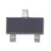
LM4051AIM3-ADJ National Semiconductor, LM4051AIM3-ADJ Datasheet - Page 3

LM4051AIM3-ADJ
Manufacturer Part Number
LM4051AIM3-ADJ
Description
IC, SM, ADJUSTABLE, VOLT REF, 0.1%
Manufacturer
National Semiconductor
Datasheet
1.LM4051AIM3-ADJ.pdf
(14 pages)
Specifications of LM4051AIM3-ADJ
Rohs Compliant
YES
Available stocks
Company
Part Number
Manufacturer
Quantity
Price
V
I
∆V
∆V
Z
e
∆V
V
RMIN
Symbol
R
N
R
HYST
Absolute Maximum Ratings
If Military/Aerospace specified devices are required,
please contact the National Semiconductor Sales Office/
Distributors for availability and specifications.
LM4051-1.2
Electrical Characteristics
Boldface limits apply for T
verse Breakdown Voltage tolerances of
Reverse Current
Forward Current
Maximum Output Voltage
Power Dissipation (T
Storage Temperature
Lead Temperature
M3 Packages
ESD Susceptibility
R
R
R
/∆T
/∆I
(LM4051-ADJ)
M3 Package
Vapor phase (60 seconds)
Infrared (15 seconds)
R
Reverse Breakdown Voltage
Reverse Breakdown Voltage
Tolerance (Note 6)
Minimum Operating Current
Average Reverse Breakdown
Voltage Temperature
Coefficient (Note 6)
Reverse Breakdown Voltage
Change with Operating
Current Change
Reverse Dynamic Impedance
Wideband Noise
Reverse Breakdown Voltage
Long Term Stability
(Note 9)
Thermal Hysteresis
(Note 10)
Parameter
A
= 25˚C) (Note 2)
A
= T
J
= T
I
I
Industrial Temp. Range
Extended Temp. Range
I
I
I
∆T = −40˚C to 125˚C
I
1 mA ≤ I
I
I
10 Hz ≤ f ≤ 10 kHz
t = 1000 hrs
T = 25˚C
I
∆T = −40˚C to 125˚C
R
R
R
R
R
RMIN
R
R
R
MIN
= 10 mA
= 100 µA
= 100 µA
= 1 mA
= 100 µA
= 1 mA, f = 120 Hz
= 100 µA
= 100 µA
±
−65˚C to +150˚C
0.1%,
≤ I
to T
Conditions
R
R
±
≤ 1 mA
≤ 12 mA
(Note 1)
MAX
0.1˚C
±
0.2% and
280 mW
; all other limits T
+215˚C
+220˚C
20 mA
10 mA
15V
±
0.5% respectively.
3
(Note 4)
Typical
1.225
0.36
±
±
±
120
0.3
1.8
0.5
39
20
20
15
15
Operating Ratings
See AN-450 “Surface Mounting Methods and Their Effect
on Product Reliability” for other methods of soldering
surface mount devices.
Temperature Range
Industrial Temperature Range
Extended Temperature Range
Reverse Current
Output Voltage Range
A
Human Body Model (Note 3)
Machine Model (Note 3)
LM4051-1.2
LM4051-ADJ
LM4051-ADJ
= T
LM4051AEM3
LM4051AIM3
J
(Note 5)
= 25˚C. The grades A, B and C designate initial Re-
(Limits)
±
±
±
±
1.1
1.5
6.0
8.0
60
65
1.2
5.2
7.4
50
LM4051BEM3
LM4051BIM3
(Note 5)
(Limits)
±
±
±
±
1.1
1.5
6.0
8.0
60
65
2.4
6.4
8.6
50
(Note 2)
LM4051CEM3
LM4051CIM3
(Note 5)
−40˚C ≤ T
(Limts)
±
±
−40˚C ≤ T
±
1.1
1.5
6.0
8.0
±
10.1
12.2
60
65
50
(T
6
min
60 µA to 12 mA
60 µA to 12 mA
1.24V to 10V
≤ T
A
www.national.com
A
ppm/˚C (max)
A
≤ +125˚C
≤ +85˚C
mV (max)
mV (max)
mV (max)
mV (max)
mV (max)
mV (max)
mV (max)
µA (max)
µA (max)
≤ T
ppm/˚C
ppm/˚C
(Limit)
Units
µV
mV/V
ppm
200V
mV
mV
µA
2 kV
Ω
V
max
rms
)


