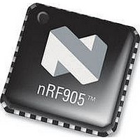
NRF905 NORDIC SEMICONDUCTOR, NRF905 Datasheet - Page 3

NRF905
Manufacturer Part Number
NRF905
Description
IC, TRANSCEIVER, 430 928MHZ, SMD
Manufacturer
NORDIC SEMICONDUCTOR
Datasheet
1.NRF905.pdf
(42 pages)
Specifications of NRF905
Transmitting Current
9mA
Data Rate
50Kbps
Frequency Range
430MHz To 928MHz
Modulation Type
GFSK
Sensitivity Dbm
-100dBm
Rf Ic Case Style
QFN
No. Of Pins
32
Supply Voltage Range
1.9V To 3.6V
Output Power
10dBm
Rohs Compliant
Yes
Lead Free Status / RoHS Status
Lead free / RoHS Compliant
Available stocks
Company
Part Number
Manufacturer
Quantity
Price
Part Number:
NRF905
Manufacturer:
NORDIC
Quantity:
20 000
Company:
Part Number:
NRF905-REEL
Manufacturer:
NORDIC
Quantity:
20 000
Part Number:
NRF905-REEL
Manufacturer:
NORDIC
Quantity:
20 000
Company:
Part Number:
NRF905C
Manufacturer:
NORDIC
Quantity:
10 615
PRODUCT SPECIFICATION
nRF905 Single Chip 433/868/915 MHz Radio Transceiver
TABLE OF CONTENTS
1
2
3
4
5
6
7
8
9
10
11
12
13
14
Main office: Nordic Semiconductor ASA
Revision: 1.4
5.1
5.2
5.3
5.4
5.5
5.6
5.7
6.1
6.2
6.3
6.4
6.5
7.1
7.2
7.3
7.4
7.5
8.1
8.2
8.3
8.4
8.5
8.6
8.7
8.8
9.1
9.2
9.3
9.4
9.5
10.1
11.1
11.2
11.3
11.4
Pin Functions .................................................................................................................... 4
Pin Assignment................................................................................................................. 5
Electrical Specifications ................................................................................................... 6
Current Consumption........................................................................................................ 8
Modes of Operation .......................................................................................................... 9
Device Configuration...................................................................................................... 15
Important Timing Data ................................................................................................... 21
Peripheral RF Information .............................................................................................. 24
nRF905 features.............................................................................................................. 28
Package Outline.......................................................................................................... 30
Application Examples ................................................................................................ 32
Absolute Maximum Ratings....................................................................................... 38
Glossary of Terms ...................................................................................................... 39
Definitions .................................................................................................................. 40
Active Modes ........................................................................................................... 9
Power Saving Modes ............................................................................................... 9
nRF ShockBurst™ Mode......................................................................................... 9
Typical ShockBurst
Typical ShockBurst
Power Down Mode ................................................................................................ 14
Standby Mode ........................................................................................................ 14
SPI Register Configuration .................................................................................... 15
SPI Instruction Set ................................................................................................. 16
SPI Timing ............................................................................................................. 17
RF – Configuration Register Description .............................................................. 19
Register Contents ................................................................................................... 20
Device Switching Times ........................................................................................ 21
ShockBurst
ShockBurstTM RX timing ..................................................................................... 22
Preamble ................................................................................................................ 22
Time On Air ........................................................................................................... 23
Crystal Specification .............................................................................................. 24
External Clock Reference ...................................................................................... 24
Microprocessor Output Clock ................................................................................ 24
Antenna Output ...................................................................................................... 25
Output Power Adjustment...................................................................................... 25
Modulation ............................................................................................................. 25
Output Frequency................................................................................................... 26
PCB Layout and Decoupling Guidelines ............................................................... 27
Carrier Detect......................................................................................................... 28
Address Match ....................................................................................................... 28
Data Ready............................................................................................................. 28
Auto Retransmit ..................................................................................................... 29
RX Reduced Power Mode...................................................................................... 29
Package marking .................................................................................................... 31
Differential Connection to a Loop Antenna........................................................... 32
PCB Layout Example; Differential Connection to a Loop Antenna...................... 33
Single ended connection to 50 antenna............................................................... 34
PCB Layout Example; Single Ended Connection to 50 Antenna ....................... 36
TM
TX timing ....................................................................................... 21
TM
TM
- Vestre Rosten 81, N-7075 Tiller, Norway
TX...................................................................................... 10
RX ..................................................................................... 12
Page 3 of 42
- Phone +4772898900 -Fax +4772898989
June 2006


