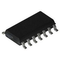
HFA3600IB Intersil, HFA3600IB Datasheet - Page 14

HFA3600IB
Manufacturer Part Number
HFA3600IB
Description
IC, LOW-NOISE AMP, 19.8DB 900MHZ SOIC-14
Manufacturer
Intersil
Datasheet
1.HFA3600IB.pdf
(16 pages)
Specifications of HFA3600IB
Frequency Range
900MHz
Noise Figure Typ
3.97dB
Power Dissipation Pd
1W
Supply Current
11.3mA
Supply Voltage Range
4V To 5.5V
Gain
19.8dB
Rf Type
Cellular, GSM, ISM, PCS
Lead Free Status / RoHS Status
Contains lead / RoHS non-compliant
Evaluation Board Testing Information
The following paragraphs contain information related to the
evaluation of the HFA3600 LNA/Mixer noise figure and
common errors encountered during individual and cascaded
performance verification. A simple cascaded arrangement
using a simple
included.
Background
Active single balanced mixers are low cost, low power
dissipation devices which require low local oscillator levels to
operate. As single balanced mixers lack high isolation from
the RF and LO input ports to the IF output and operate with
moderate feedthrough from the LO input to the RF input,
special precautions must be taken when evaluating these
devices with test set ups, specifically filtering, and cabling
hook ups. These constraints, although important during the
evaluation of the device, are not major issues in the design
of the overall system.
Poor isolation from the RF input to the IF output results in
direct amplification (not only frequency translation) of
undesired signals at the RF input port. For example, any
noise within the IF passband generated by a previous active
system block (LNA or any other amplifier) is directly
transferred and amplified to the IF output. This lack of
isolation can considerably degrade the translated signal to
noise ratio of the IF output. An image filter placed before the
mixer RF input port can solve the problem. Image filters are
normally implemented as narrow bandpass filters which are
tuned to pass only the desired (LO+IF) or (LO-IF) frequency
of interest. Consequently, the role of rejecting noise at
frequencies within the IF passband is accomplished.
Poor isolation from the LO input to IF output can also slightly
degrade the translated signal to noise ratio of the IF output in
two distinct ways: the noise generated by the local oscillator
at the IF frequency band is directly coupled to the IF port,
and the noise at the RF and image RF passbands (LO SSB
noise) gets translated to the IF passband and appears in the
IF output. To overcome these problems, the use of a band
pass filter is recommended between the local oscillator and
the LO input for optimization of the mixer noise figure.
The lack of isolation from the LO input port back to the RF
input port can cause constructive or destructive interference
at the RF port which can affect noise and conversion
(translation) gain performance.
network as an intermediate filter is
14
HFA3600
Cascaded Evaluation
The cascaded evaluation of the HFA3600 demo-board must
be carried out with a filter network between the LNA and the
mixer when noise figure or sensitivity measurements are
made. Any bandpass/highpass implementation must be
utilized to function as either an image or noise rejection filter.
To remove the IF noise being generated or amplified by the
LNA, a low cost
simple high pass filter can be used for a cascaded noise
evaluation of the HFA3600. Although this implementation
does not remove the image signal nor the image noise being
generated by the LNA, this filter gives an overall cascaded
performance that closely approximates the results obtained
by calculation. The large contribution of the LNA gain at the
IF frequency (from a white noise source at its input and its
own IF noise), to the overall noise figure measurement is
practically eliminated by the high pass filter. Figure 1 shows
an implementation of a high pass filter network used to filter
out the incoming IF noise from the LNA. A rider board can be
built to connect the LNAOUT and the RFIN SMA connectors
of the demo-board. The 1000pF decoupling capacitors are
included in the demo-board.
Tuning of the
the value of the 3.5pF capacitor. This low value of
capacitance may be dependent on the rider layout. The
value may be optimized for low insertion loss and, therefore,
for optimum cascaded noise figure.
Figure 37 and Tables 2 and 3 illustrate the overall
performance of the HFA3600 in a cascaded form at 915MHz
RF input and 75MHz IF frequency:
Saw, 3dB Loss
Short/No Filter
the RF Frequency
FIGURE 36. HFA3600 HIGH PASS FILTER IMPLEMENTATION
A “T” FILTER CAN ELIMINATE THE 1000pF COUPLING CAPACITORS
IMAGE FILTER
TABLE 2. SSB MEASUREMENT SET UP (BANDPASS
Filter, No Loss at
COMPONENTS SHOWN ARE FOR 900MHz RF
LNA
1000pF
INPUT FILTER) (NOTES 1, 3)
network, if necessary, is done by changing
SMA
or “T” high pass filter can be utilized. This
(dB)
14.4
NF
5.1
5.2
10nH
3.5pF
GAIN
(dB)
16.0
19.0
N/A
10nH
Gain reduced by the filter loss
NF degrades due to the IF
noise from the LNA
Note the increase in cascaded
gain
SMA
COMMENTS
1000pF
RF
LO
IF


