LM117H National Semiconductor, LM117H Datasheet - Page 10
LM117H
Manufacturer Part Number
LM117H
Description
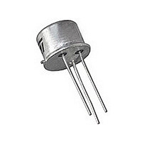
IC, ADJ LINEAR REG, 1.2V TO 37V, TO-39-3
Manufacturer
National Semiconductor
Datasheet
1.LM117H.pdf
(28 pages)
Specifications of LM117H
Primary Input Voltage
40V
Dropout Voltage Vdo
2.2V
No. Of Outputs
1
No. Of Pins
3
Output Current
500mA
Operating Temperature Range
0°C To +125°C
Voltage Regulator Type
Linear
Topology
Standard
Regulator Output Type
Adjustable
Polarity Type
Positive
Number Of Outputs
Single
Input Voltage (min)
4.2V
Input Voltage (max)
40V
Output Voltage
1.2 to 37V
Package Type
TO-39
Load Regulation
0.3%
Line Regulation
0.02%/V
Operating Temp Range
-55C to 150C
Operating Temperature Classification
Military
Pin Count
3
Mounting
Through Hole
Rohs Compliant
Yes
Lead Free Status / RoHS Status
Lead free / RoHS Compliant
Lead Free Status / RoHS Status
Lead free / RoHS Compliant
Available stocks
Company
Part Number
Manufacturer
Quantity
Price

Part Number:
LM117H
Manufacturer:
NS/国半
Quantity:
20 000
Company:
Part Number:
LM117H/883Q
Manufacturer:
AOS
Quantity:
125
Part Number:
LM117HRQMLV
Manufacturer:
NS/国半
Quantity:
20 000
Part Number:
LM117HVI
Manufacturer:
LINEAR/凌特
Quantity:
20 000


www.national.com
diodes included for use with outputs greater than 25V and
high values of output capacitance.
D1 protects against C1
D2 protects against C2
HEATSINK REQUIREMENTS
The LM317 regulators have internal thermal shutdown to pro-
tect the device from over-heating. Under all operating condi-
tions, the junction temperature of the LM317 should not
exceed the rated maximum junction temperature (T
C for the LM117, or 125°C for the LM317A and LM317. A
heatsink may be required depending on the maximum device
power dissipation and the maximum ambient temperature of
the application. To determine if a heatsink is needed, the
power dissipated by the regulator, P
Figure 4
the circuit.
The next parameter which must be calculated is the maximum
allowable temperature rise, T
where T
(150°C for the LM117, or 125°C for the LM317A/LM317), and
T
encountered in the application.
Using the calculated values for T
allowable value for the junction-to-ambient thermal resistance
(θ
A(MAX)
JA
) can be calculated:
FIGURE 3. Regulator with Protection Diodes
J(MAX)
is the maximum ambient temperature which will be
shows the voltage and currents which are present in
P
D
= ((V
is the maximum allowable junction temperature
T
R(MAX)
θ
IN
JA
− V
= (T
= T
OUT
J(MAX)
R(MAX)
) × I
R(MAX)
L
− T
/ P
) + (V
R(MAX)
A(MAX)
D
:
)
D
, must be calculated:
IN
and P
× I
G
)
D
, the maximum
906307
J
) of 150°
(2)
(3)
(4)
(5)
10
If the calculated maximum allowable thermal resistance is
higher than the actual package rating, then no additional work
is needed. If the calculated maximum allowable thermal re-
sistance is lower than the actual package rating either the
power dissipation (P
ambient temperature T
mal resistance (θ
or some combination of these.
If a heatsink is needed, the value can be calculated from the
formula:
where (θ
tween the device case and the heatsink surface, and θ
thermal resistance from the junction of the die to surface of
the package case.
When a value for θ
heatsink must be selected that has a value that is less than,
or equal to, this number.
The θ
ufacturer in the catalog, or shown in a curve that plots tem-
perature rise vs power dissipation for the heatsink.
HEATSINKING SURFACE MOUNT PACKAGES
The TO-263 (S), SOT-223 (EMP) and TO-252 (MDT) pack-
ages use a copper plane on the PCB and the PCB itself as a
heatsink. To optimize the heat sinking ability of the plane and
PCB, solder the tab of the package to the plane.
HEATSINKING THE SOT-223 PACKAGE
Figure 5
package.
copper and 51°C/W for 2 ounce copper and a maximum junc-
tion temperature of 125°C. Please see AN-1028 for thermal
enhancement techniques to be used with SOT-223 and
TO-252 packages.
(H−A)
CH
and
FIGURE 4. Power Dissipation Diagram
Figure 6
rating is specified numerically by the heatsink man-
is the thermal resistance of the contact area be-
Figure 6
θ
HA
JA
(H−A)
≤
assumes a θ
) must be lowered by adding a heatsink,
D
(θ
) needs to be reduced, the maximum
show the information for the SOT-223
A(MAX)
JA
is found using the equation shown, a
- (θ
CH
needs to be reduced, the ther-
+ θ
(J−A)
JC
of 74°C/W for 1 ounce
))
906360
JC
(6)
is
Related parts for LM117H
Image
Part Number
Description
Manufacturer
Datasheet
Request
R

Part Number:
Description:
LM117 - 3-Terminal Adjustable Regulator, Package: TO-3, Pin Nb=3
Manufacturer:
National Semiconductor Corporation
Datasheet:

Part Number:
Description:
LM117/LM317A/LM317 3-Terminal Adjustable Regulator; ; Container: Tray
Manufacturer:
National Semiconductor
Datasheet:
Part Number:
Description:
National Semiconductor [8-Bit D/A Converter]
Manufacturer:
National Semiconductor
Datasheet:
Part Number:
Description:
National Semiconductor [Media Coprocessor]
Manufacturer:
National Semiconductor
Datasheet:
Part Number:
Description:
Digitally Controlled Tone and Volume Circuit with Stereo Audio Power Amplifier, Microphone Preamp Stage and National 3D Sound
Manufacturer:
National Semiconductor
Datasheet:
Part Number:
Description:
Digitally Controlled Tone and Volume Circuit with Stereo Audio Power Amplifier, Microphone Preamp Stage and National 3D Sound
Manufacturer:
National Semiconductor
Datasheet:
Part Number:
Description:
AC97 Rev 2 Codec with Sample Rate Conversion and National 3D Sound
Manufacturer:
National Semiconductor
Part Number:
Description:
Manufacturer:
National Semiconductor
Datasheet:
Part Number:
Description:
Manufacturer:
National Semiconductor
Datasheet:
Part Number:
Description:
General Purpose, Low Voltage, Low Power, Rail-to-Rail Output Operational Amplifiers
Manufacturer:
National Semiconductor
Datasheet:
Part Number:
Description:
8-bit 20 MSPS flash A/D converter.
Manufacturer:
National Semiconductor
Datasheet:
Part Number:
Description:
Low Noise Quad Operational Amplifier
Manufacturer:
National Semiconductor
Datasheet:
Part Number:
Description:
Quad Differential Line Receivers
Manufacturer:
National Semiconductor
Datasheet:
Part Number:
Description:
Quad High Speed Trapezoidal? Bus Transceiver
Manufacturer:
National Semiconductor
Datasheet: