NTE1911 NTE ELECTRONICS, NTE1911 Datasheet

IC, NEGATIVE ADJ REG, -1.2V TO -37V, TO3

NTE1911

Manufacturer Part Number
NTE1911
Description
IC, NEGATIVE ADJ REG, -1.2V TO -37V, TO3
Manufacturer
NTE ELECTRONICS
Datasheet

Specifications of NTE1911

Primary Input Voltage
40V
Output Voltage Adjustable Range
-1.2V To -37V
No. Of Outputs
1
No. Of Pins
3
Output Current
1.5A
Operating Temperature Range
-55°C To +150°C
Description:
The NTE1911 is an adjustable 3–terminal negative voltage regulator capable of supplying in excess
of 1.5A over an output voltage range of –1.2V to 37V. This regulator is exceptionally easy to apply,
requiring only 2 external resistors to set the output voltage and 1 output capacitor for frequency com-
pensation. The circuit design has been optimized for excellent regulation and low thermal transients.
Further, if features internal current limiting, thermal shutdown and safe–area compensation, making
the, virtually blowout–proof against overloads.
The NTE1911 serves a wide variety of applications including local on–card regulation, program-
mable–output voltage regulation or precision current regulation.
Features:
D Output Voltage Adjustable from –1.2V to –37V
D 1.5A Output Current Guaranteed, –55 C to +150 C
D Line Regulation Typically 0.01%/V
D Load Regulation Typically 0.3%
D Excellent Thermal Regulation, 0.002%/W
D 77dB Ripple Rejection
D Excellent Rejection of Thermal Transients
D 50ppm/ C Temperature Coefficient
D Temperature–Independent Current Limit
D Internal Thermal Overload Protection
Absolute Maximum Ratings:
Power Dissipation, P
Input–Output Voltage Differential, V
Operating Junction Temperature Range, T
Storage Temperature Range, T
Lead Temperature (Soldering, 10 sec), T
Electrical Characteristics: (Note 1)
Note 1. Unless otherwise noted, these specifications apply: 0
Note 2. Load and line regulation are specified at constant junction temperature. Pulse testing with
Line Regulation
P
a low duty cycle is used. Change in V
mal Regulation specification.
Parameter
max
3 Terminal Adjustable Negative Voltage Regulator
= 20W, and I
D
. . . . . . . . . . . . . . . . . . . . . . . . . . . . . . . . . . . . . . . . . . . . . . . . . . . . . . . . . . . . .
MAX
Symbol
Reg
stg
= 1.5A.
line
. . . . . . . . . . . . . . . . . . . . . . . . . . . . . . . . . . . . . . . . . .
I–O
–1.2V to –37V, 1.5A
T
3V
A
= +25 C, 3V
. . . . . . . . . . . . . . . . . . . . . . . . . . . . . . . . . . . . . . . . . . . . . . . .
L
V
I
J
NTE1911
. . . . . . . . . . . . . . . . . . . . . . . . . . . . . . . . . . . . . . . . . . .
– V
. . . . . . . . . . . . . . . . . . . . . . . . . . . . . . . . . . . .
O
O
Test Conditions
because of heating effects is covered under the Ther-
40V, Note 2
V
I
– V
O
40V, Note 2
T
J
+125 C, (V
Min
0.01
0.02
Typ
I
–65 to +150 C
–V
Max
0.04
0.07
0 to +125 C
O
) = 5V,
300 C
Unit
%/V
%/V
20W
40V

Related parts for NTE1911

NTE1911 Summary of contents

Page 1

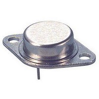
... Terminal Adjustable Negative Voltage Regulator Description: The NTE1911 is an adjustable 3–terminal negative voltage regulator capable of supplying in excess of 1.5A over an output voltage range of –1.2V to 37V. This regulator is exceptionally easy to apply, requiring only 2 external resistors to set the output voltage and 1 output capacitor for frequency com- pensation. The circuit design has been optimized for excellent regulation and low thermal transients. Further, if features internal current limiting, thermal shutdown and safe– ...

Page 2

Electrical Characteristics (Cont’d): (Note 1) Parameter Symbol Load Regulation Reg Thermal Regulation Reg Adjustment Pin Current Adjustment Pin Current Change Reference Voltage Temperature Stability Minimum Load Current Maximum Output Current Limit RMS Noise Ripple Rejection Ratio ...

Related keywords