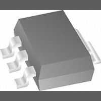
LM1117MPX-1.8 National Semiconductor, LM1117MPX-1.8 Datasheet

LM1117MPX-1.8
Specifications of LM1117MPX-1.8
Available stocks
Related parts for LM1117MPX-1.8
LM1117MPX-1.8 Summary of contents
Page 1
... General Description The LM1117 is a series of low dropout voltage regulators with a dropout of 1.2V at 800mA of load current. It has the same pin-out as National Semiconductor’s industry standard LM317. The LM1117 is available in an adjustable version, which can set the output voltage from 1.25V to 13.8V with only two external resistors ...
Page 2
... TO-252 0˚C to +125˚C −40˚C to +125˚C 8-lead LLP 0˚C to +125˚C −40˚C to 125˚C TO-263 0˚C to +125˚C www.national.com Part Number Packaging Marking LM1117MPX-ADJ N03A LM1117MPX-1.8 N12A LM1117MPX-2.5 N13A LM1117MPX-2.85 N04A LM1117MPX-3.3 N05A LM1117MPX-5.0 N06A LM1117IMPX-ADJ N03B LM1117IMPX-3.3 N05B LM1117IMPX-5 ...
Page 3
Block Diagram Connection Diagrams SOT-223 10091904 Top View TO-220 Top View TO-252 10091938 Top View 10091902 When using the LLP package Pins 2, 3 & 4 must be connected together and Pins 5, 6 & 7 must be connected together ...
Page 4
... Absolute Maximum Ratings If Military/Aerospace specified devices are required, please contact the National Semiconductor Sales Office/ Distributors for availability and specifications. Maximum Input Voltage (V to GND) IN Power Dissipation (Note 2) Junction Temperature ( (Note 2) Storage Temperature Range Lead Temperature LM1117 Electrical Characteristics Typicals and limits appearing in normal type apply for T tion temperature range for operation, 0˚ ...
Page 5
LM1117 Electrical Characteristics Typicals and limits appearing in normal type apply for T tion temperature range for operation, 0˚C to 125˚C. Symbol Parameter ∆V Load Regulation LM1117-ADJ OUT (Note LM1117-1 LM1117-2 LM1117-2.85 V ...
Page 6
LM1117I Electrical Characteristics Typicals and limits appearing in normal type apply for T tion temperature range for operation, −40˚C to 125˚C. Symbol Parameter V Reference Voltage LM1117I-ADJ REF I 10mA ≤ I ≤ 10V V Output Voltage LM1117I-3.3 OUT I ...
Page 7
Note 2: The maximum power dissipation is a function –T )/θ . All numbers apply for packages soldered directly into a PC board. D J(max Note 3: For testing purposes, ESD was applied ...
Page 8
Typical Performance Characteristics LM1117-ADJ Ripple Rejection vs. Current Adjust Pin Current LM1117-5.0 Load Transient Response www.national.com (Continued) Temperature Stability 10091907 LM1117-2.85 Load Transient Response 10091926 LM1117-2.85 Line Transient Response 10091909 8 10091925 10091908 10091910 ...
Page 9
Typical Performance Characteristics LM1117-5.0 Line Transient Response Application Note 1.0 EXTERNAL CAPACITORS/STABILITY 1.1 Input Bypass Capacitor An input capacitor is recommended. A 10µF tantalum on the input is a suitable input bypassing for almost all applications. 1.2 Adjust Terminal Bypass ...
Page 10
Application Note (Continued) FIGURE 2. Typical Application using Fixed Output Regulator When the adjustable regulator is used (Figure 3), the best performance is obtained with the positive side of the resistor R1 tied directly to the output terminal of the ...
Page 11
Application Note (Continued) FIGURE 5. Cross-sectional view of Integrated Circuit Mounted on a printed circuit board. Note that the case temperature is measured at the point where the leads contact with the mounting pad surface The LM1117 regulators have internal ...
Page 12
Application Note (Continued) Layout 14 0.284 15 0.392 16 *Tab of device attached to topside copper www.national.com TABLE 1. θ Different Heatsink Area (Continued) JA Copper Area 0.284 0.392 0.5 0.5 12 Thermal Resistance ...
Page 13
Application Note (Continued) FIGURE 7. θ vs. 1oz Copper Area for SOT-223 JA FIGURE 8. θ vs. 2oz Copper Area for TO-252 JA FIGURE 9. Maximum Allowable Power Dissipation vs. Ambient Temperature for SOT-223 FIGURE 10. Maximum Allowable Power Dissipation ...
Page 14
Application Note (Continued) FIGURE 13. Top View of the Thermal Test Pattern in Actual Scale www.national.com 10091941 14 ...
Page 15
Application Note (Continued) FIGURE 14. Bottom View of the Thermal Test Pattern in Actual Scale 10091942 15 www.national.com ...
Page 16
Typical Application Circuits Adjusting Output of Fixed Regulators Regulator with Reference 1.25V to 10V Adjustable Regulator with Improved Ripple Rejection www.national.com 10091930 5V Logic Regulator with Electronic Shutdown* 10091931 10091929 16 10091927 ...
Page 17
Typical Application Circuits (Continued) Battery Backed-Up Regulated Supply Low Dropout Negative Supply 17 10091932 10091933 www.national.com ...
Page 18
Physical Dimensions www.national.com inches (millimeters) unless otherwise noted 3-Lead SOT-223 NS Package Number MP04A 3-Lead TO-220 NS Package Number T03B 18 ...
Page 19
Physical Dimensions inches (millimeters) unless otherwise noted (Continued) 3-Lead TO-263 NS Package Number TS3B 19 www.national.com ...
Page 20
Physical Dimensions www.national.com inches (millimeters) unless otherwise noted (Continued) 3-Lead TO-252 NS Package Number TD03B 8-Lead LLP NS Package Number LDC08A 20 ...
Page 21
... BANNED SUBSTANCE COMPLIANCE National Semiconductor manufactures products and uses packing materials that meet the provisions of the Customer Products Stewardship Specification (CSP-9-111C2) and the Banned Substances and Materials of Interest Specification (CSP-9-111S2) and contain no ‘‘Banned Substances’’ as defined in CSP-9-111S2. ...


