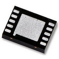
LM5030SD National Semiconductor, LM5030SD Datasheet - Page 3

LM5030SD
Manufacturer Part Number
LM5030SD
Description
IC, DC-DC, CNTRL, PUSH-PULL, 10LLP
Manufacturer
National Semiconductor
Datasheet
1.LM5030SD.pdf
(12 pages)
Specifications of LM5030SD
Primary Input Voltage
90V
No. Of Outputs
2
Voltage Regulator Case Style
LLP
No. Of Pins
10
Operating Temperature Range
-40°C To +105°C
Svhc
No SVHC (15-Dec-2010)
Base
RoHS Compliant
Package / Case
LLP
Available stocks
Company
Part Number
Manufacturer
Quantity
Price
Pin Description
Pin Name
COMP
OUT1
OUT2
GND
DAP
LLP
V
Vcc
V
CS
RT
SS
FB
IN
Number
SUB
Pin
10
1
2
3
4
5
6
7
8
9
Source Input Voltage
Inverting input to the error amplifier The non-inverting input is internally connected to a 1.25 Volt
Output to the error amplifier
Output from the internal high
voltage series pass regulator. The
regulation setpoint is 7.7 Volts.
Output of the PWM controller
Output of the PWM controller
Return
Current sense input
Oscillator timing resistor pin and
synchronization input.
Dual purpose Softstart and
Shutdown pin
Die Substrtae
Description
Input to start-up regulator. Input range 14 to 100 Volts.
reference.
There is an internal 5K resistor pull-up on this pin. The error
amplifier provides an active sink.
If an auxiliary winding raises the voltage on this pin above the
regulation setpoint the internal series pass regulator will
shutdown, reducing the IC power dissipation.
Alternating PWM output gate driver.
Alternating PWM output gate driver.
Ground
Current sense input for current mode control and current limit
sensing. Using separate dedicated comparators, if CS exceeds
0.5 Volt the outputs will go into Cycle by Cycle current limit. If CS
exceeds 0.625V the outputs will be disabled and a softstart
commenced.
An external resistor sets the oscillator frequency. This pin will
also accept synchronization pulses from an external oscillator.
A 10µA current source and an external capacitor set the softstart
timing length. The controller will enter a low power state if the SS
pin is pulled below the typical shutdown threshold of 0.45V.
The exposed die attach pad on the LLP package should be
connected to a PCB thermal pad at ground potential. For
additional information on using National Semiconductor’s No Pull
Back LLP package, please refer to LLP Application Note
AN-1187.
3
Application Information
www.national.com


