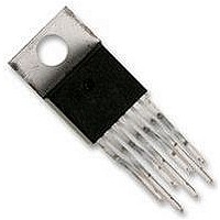
LM2599T-5.0 National Semiconductor, LM2599T-5.0 Datasheet - Page 19

LM2599T-5.0
Manufacturer Part Number
LM2599T-5.0
Description
SWITCHING REG 3A 5.0V, 2599, TO-220
Manufacturer
National Semiconductor
Datasheet
1.LM2599T-12.pdf
(32 pages)
Specifications of LM2599T-5.0
Primary Input Voltage
12V
No. Of Outputs
1
Output Voltage
5V
Output Current
3A
Voltage Regulator Case Style
TO-220
No. Of Pins
7
Operating Temperature Range
-40°C To +125°C
Svhc
No SVHC
Lead Free Status / RoHS Status
Lead free / RoHS Compliant
Available stocks
Company
Part Number
Manufacturer
Quantity
Price
Company:
Part Number:
LM2599T-5.0
Manufacturer:
NS
Quantity:
500
Application Information
the narrow pulses and ramp up in a controlled manner. This
is a very useful feature in some switcher topologies that
require large startup currents (such as the inverting configu-
ration) which can load down the input power supply.
Note: The lower curve shown in Figure 13 shows the Soft-start region from
4. Normal operation. Above 2.8V, the circuit operates as a
standard Pulse Width Modulated switching regulator. The
capacitor will continue to charge up until it reaches the
internal clamp voltage of approximately 7V. If this pin is
driven from a voltage source, the current must be limited to
about 1 mA.
If the part is operated with an input voltage at or below the
internal soft-start clamp voltage of approximately 7V, the
voltage on the SD/SS pin tracks the input voltage and can be
disturbed by a step in the voltage. To maintain proper func-
tion under these conditions, it is strongly recommended that
the SD/SS pin be clamped externally between the 3V maxi-
mum soft-start threshold and the 4.5V minimum input volt-
age. Figure 15 is an example of an external 3.7V (approx.)
clamp that prevents a line-step related glitch but does not
interfere with the soft-start behavior of the device.
0% to 100%. This is not the duty cycle percentage, but the output
voltage percentage. Also, the Soft-start voltage range has a negative
temperature coefficient associated with it. See the Soft-start curve in
the electrical characteristics section.
FIGURE 14. Timing Diagram for 5V Output
(Continued)
19
FIGURE 13. Soft-start, Delay, Error, Output
DS012582-32
www.national.com
DS012582-31


