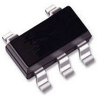
AS1323BTTT-27 austriamicrosystems, AS1323BTTT-27 Datasheet

AS1323BTTT-27
Specifications of AS1323BTTT-27
Related parts for AS1323BTTT-27
AS1323BTTT-27 Summary of contents
Page 1
... The device is available in a TSOT23-5 pin package. Figure 1. Typical Operating Circuit 10µH 1 VBATT 10µF AS1323 3 SHDNN www.austriamicrosystems.com 2 Key Features ! 1.6µA Quiescent Current ! Input Voltage Range: 0. 100mA Output Current ! Fixed Output Voltages: 2.7, 3.0 and 3. Shutdown Current: 0.1µ ...
Page 2
... Shutdown mode. 3 SHDNN 1 = Normal operating mode. Output. This pin also supplies bootstrap power to the device. 4 VOUT Inductor Connection. This pin is connected to the internal N-channel MOSFET switch 5 LX drain and P-channel synchronous rectifier drain. www.austriamicrosystems.com VBATT AS1323 VSS 2 SHDNN 3 4 VOUT Description Revision 1 ...
Page 3
... Table 3. Absolute Maximum Ratings Parameter VBATT, SHDNN VSS Maximum Current VOUT, LX Thermal Resistance Θ JA Electro-Static Discharge Operating Temperature Range Storage Temperature Range Junction Temperature Package Body Temperature www.austriamicrosystems.com may cause permanent damage to the device. These are stress ratings only, Min Max Units -0 207.4 º ...
Page 4
... Shutdown Current into I SDI-BAT V BATT SHDNN Voltage Threshold Low SHDNN Voltage Threshold High I SHDNN Input Bias Current T SDI completely disconnected (0V) during shutdown. OUT www.austriamicrosystems.com = V , SHDNN = OUT OUT(NOM) OUT LOAD Condition T = 25ºC AMB T = 25ºC, AMB R = 100Ω LOAD AS1323-27 AS1323-30 ...
Page 5
... Output Current (m A) Figure 7. Output Voltage vs. Temperature 3.32 3.315 No Load 3.31 3.305 3 10mA LOAD 3.295 3. 30mA LOAD 3.285 3.28 -50 - Tem perature (°C) www.austriamicrosystems.com = 10mA 1.5V; unless otherwise specified. LOAD BATT = 3.3V Figure 4. Efficiency vs. Output Current; V OUT 1. 1. 0.95V 0.1 100 = 2.7V Figure 6 ...
Page 6
... OUT 3.04 3. 10mA OUT 3 2. 30mA OUT 2.96 2.94 2.92 2.9 0.75 1 1.25 1.5 Input Voltage (V) www.austriamicrosystems.com Figure 10. Shutdown Current vs. Temperature 1000 100 10 1 0.1 1.6 1.7 -50 -25 Figure 12. Output Voltage vs. Input Voltage 2.7V OUT 2.78 2.76 2.74 2.72 2.7 2.68 2 ...
Page 7
... Figure 15. Output Current vs. Input Voltage 110 100 3.0V OUT 3.3V OUT OUT 0.75 1 1.25 1.5 Input Voltage (V) Figure 17. Switching Waveform; V OUT 200µs/Div www.austriamicrosystems.com Figure 16. Switching Waveform 2.7V 1. 3.0V Figure 18. Switching Waveform; V Revision 1.04 = 2.7V OUT 200µs/Div = 3.3V OUT 200µs/Div ...
Page 8
... The AS1323 enter shutdown when the SHDNN pin is driven low. During shutdown, the output is completely discon- nected from the battery. Shutdown can be pulled as high as 3.6V, regardless of the voltage at pins V normal operation, connect SHDN to the input. www.austriamicrosystems.com 8). The AS1323 also features an active-low shut- L1 ...
Page 9
... The inductor’s incremental saturation current rating should be greater than the peak switching current. However generally advisable to bias the inductor into saturation by as much as 20%, although this will slightly reduce efficiency. Maximum Output Current The maximum output current (I OUTMAX the formula for determining I : OUTMAX www.austriamicrosystems.com 10µ VBATT LX 10µF 2 ...
Page 10
... Note: For the optimal performance the IC’s VSS and the ground leads of the input and output capacitors must be kept less than 5mm apart using a ground plane. In addition, keep all connections to COIL as short as possible. The system robustness guarantees a reliable operation even if those recommendations are not fully applied. www.austriamicrosystems.com = ...
Page 11
... The package top can be smaller than the package bottom. Dimensions D and E1 are determined at the outer- most extremes of the plastic body exclusive of mold flash, tie bar burrs, gate burrs, and interlead flash, but include any mistmatches between the top of the package body and the bottom. D and E1 are determined at datum H. www.austriamicrosystems.com Max Notes Symbol 1 ...
Page 12
... AS1323 Data Sheet - Tape and Reel Pin1 Orientation Figure 22. Tape&Reel Pin1 Orientation Top, Through View TSOT23-5 www.austriamicrosystems.com User direction of feed TSOT23-5 TSOT23-5 TSOT23-5 Revision 1. ...
Page 13
... AS1323-BTTT-30 ASMP 3.0V AS1323-BTTT-33 ASMQ 3.3V All devices are RoHS compliant and free of halogene substances. www.austriamicrosystems.com Table 5. Description 1.6µA Quiescent Current, Single Cell, DC-DC Step-up Converter 1.6µA Quiescent Current, Single Cell, DC-DC Step-up Converter 1.6µA Quiescent Current, Single Cell, DC-DC Step-up Converter Revision 1 ...
Page 14
... The information furnished here by austriamicrosystems AG is believed to be correct and accurate. However, austriamicrosystems AG shall not be liable to recipient or any third party for any damages, including but not limited to personal injury, property damage, loss of profits, loss of use, interruption of business or indirect, special, incidental or consequential damages, of any kind, in connection with or arising out of the furnishing, performance or use of the tech- nical data herein ...


