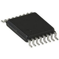
SI9731DQ-T1 Vishay, SI9731DQ-T1 Datasheet - Page 9

SI9731DQ-T1
Manufacturer Part Number
SI9731DQ-T1
Description
IC, BATTERY CHARGER, TSSOP-16
Manufacturer
Vishay
Type
Charge Controllerr
Datasheet
1.SI9731DQ-T1.pdf
(10 pages)
Specifications of SI9731DQ-T1
Output Voltage
4.1V
No. Of Pins
16
Operating Temperature Range
-40°C To +85°C
Peak Reflow Compatible (260 C)
No
Leaded Process Compatible
No
Battery Type
Li-Ion/NiCD/NiMH
Output Current
1.2A
Operating Temp Range
-40C to 85C
Package Type
TSSOP
Mounting
Surface Mount
Pin Count
16
Operating Temperature Classification
Industrial
Maximum Operating Temperature
+ 85 C
Minimum Operating Temperature
- 40 C
Package / Case
TSSOP-16
Mounting Style
SMD/SMT
Lead Free Status / RoHS Status
Contains lead / RoHS non-compliant
Available stocks
Company
Part Number
Manufacturer
Quantity
Price
Company:
Part Number:
SI9731DQ-T1
Manufacturer:
Infineon
Quantity:
12 000
Company:
Part Number:
SI9731DQ-T1-E3
Manufacturer:
FUJI
Quantity:
3 000
Part Number:
SI9731DQ-T1-E3
Manufacturer:
VISHAY/威世
Quantity:
20 000
DETAIL OPERATIONAL DESCRIPTION
4.1 V
The Si9731’s internal feedback resistors are set to provide
4.2 V charge termination at V
open circuit. Connecting the 4.1 V
Si9731 for 4.1 V charge termination at V
allows Si9731 to accommodate Li-ion batteries requiring
4.1 V or 4.2 V charge termination. Caution: the 4.1 V
should not be connected to ground or any other voltage
source as this will cause the Si9731 to operate open loop and
can result in over charging the battery!
Feedback Disconnect Switch
The Si9731 includes a feedback disconnect switch (Q5 in
Figure 1) connected in series with the device’s internal
feedback resistor string. The 42 kΩ feedback resistor string
is connected to ground when both the internal "OK to
Charge" signal and the CVMODE pin are at logic high,
providing feedback voltage to Si9731’s error amplifier. This
action helps prevent the Si9731 from discharging the battery.
CHARGERPRESENT and CHARGERPOWERON
CHARGERPRESENT and CHARGERPOWERON are open
drain outputs, each requiring an external pull-up resistor.
CHARGERPRESENT
CHARGERPRESENTIN pin goes high, signaling the
processor
CHARGERPOWERON
CHARGERPOWERONIN Pin is high, charger voltage is not
in UVLO and the battery voltage has increased to above
3.24 V, turning on the system power supply since the battery
has been charged up to minimum operating voltage.
Input Over-Voltage Detector
The external dc source connected to the V
should be at 12 V or less. In the unlikely event that the
voltage at V
Si9731’s internal over voltage detector will turn off MOSFETs
Q1, Q2, and Q5 and disable charging.
Vishay Siliconix maintains worldwide manufacturing capability. Products may be manufactured at one of several qualified locations. Reliability data for Silicon
Technology and Package Reliability represent a composite of all qualified locations. For related documents such as package/tape drawings, part marking, and
reliability data, see www.vishay.com/ppg?71321.
Document Number: 71321
S09-2249-Rev. C, 26-Oct-09
TAP
CHARGER
that
a
pin is at or above 12.8 V (typical),
charger
pin
Pin
BAT+
output if the 4.1 V
TAP
has
goes
goes
to V
BAT+
been
BAT+
low
. This feature
CHARGER
low
configures
TAP
inserted.
when
is left
with
TAP
pin
Thermal Shutdown
Si9731 also includes a thermal protection circuit that
suspends charging through Q1 and Q2 when die
temperature exceeds 130 °C due to overheating. Once the
die temperature cools to below 120 °C, the charging will
resume.
Shutdown
Si9731 can be completely turned off by applying 0.4 V or less
to the device’s ON/OFF pin. In shutdown mode, Si9731
draws less than 1 µA quiescent current with charger voltage
below UVLO, and draws 500 µA when charger voltage is
above UVLO. The device is enabled by applying 1.5 V to
12 V at the ON/OFF pin. In applications where the device will
always remain enabled, the ON/OFF pin may be connected
to the V
hysteresis, as such the device will operate properly even if a
slow moving signal is applied to the ON/OFF pin. When the
device is enabled, the battery voltage sense circuitry draws
approximately 25 µA from V
OK to Charge (OTC)
Si9731 also includes an internal signal that enables both
trickle charge mode and fast charge mode operations, the
"OK to Charge" (or OTC) signal. The OTC signal is at logic
high if all of the following are satisfied:
1. Battery voltage is below 5 V
2. Charger voltage is greater than 2.6 V but below 12.8 V
3. V
4. ON/OFF pin is at logic high.
In order to charge the battery in any manner, the OTC signal
has to be high.
V
Low
High
CHARGER
CHARGER
CHARGER
> V
> V
BAT
BAT
pin. Si9731’s shutdown circuitry includes
+ 40 mV when MAINCHARGEEN =
- 40 mV when MAINCHARGEEN =
BAT
.
Vishay Siliconix
www.vishay.com
Si9731
9


