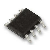
SST25VF080B-50-4I-S2AF SILICON STORAGE TECHNOLOGY, SST25VF080B-50-4I-S2AF Datasheet - Page 11

SST25VF080B-50-4I-S2AF
Manufacturer Part Number
SST25VF080B-50-4I-S2AF
Description
IC, FLASH, 8MBIT, 50MHZ, SOIC-8
Manufacturer
SILICON STORAGE TECHNOLOGY
Datasheet
1.SST25VF080B-50-4I-S2AF.pdf
(28 pages)
Specifications of SST25VF080B-50-4I-S2AF
Memory Type
Flash
Memory Size
8Mbit
Memory Configuration
1M X 8
Ic Interface Type
SPI
Clock Frequency
50MHz
Supply Voltage Range
2.7V To 3.6V
Memory Case Style
SOIC
No. Of Pins
8
Lead Free Status / RoHS Status
Lead free / RoHS Compliant
Available stocks
Company
Part Number
Manufacturer
Quantity
Price
Part Number:
SST25VF080B-50-4I-S2AF
Manufacturer:
MICROCHIP/微芯
Quantity:
20 000
Company:
Part Number:
SST25VF080B-50-4I-S2AF-T
Manufacturer:
SST
Quantity:
12 000
8 Mbit SPI Serial Flash
SST25VF080B
Byte-Program
The Byte-Program instruction programs the bits in the
selected byte to the desired data. The selected byte must
be in the erased state (FFH) when initiating a Program
operation. A Byte-Program instruction applied to a pro-
tected memory area will be ignored.
Prior to any Write operation, the Write-Enable (WREN)
instruction must be executed. CE# must remain active low
for the duration of the Byte-Program instruction. The Byte-
©2006 Silicon Storage Technology, Inc.
FIGURE 6: B
YTE
-P
ROGRAM
SCK
CE#
SO
SI
MODE 3
MODE 0
S
EQUENCE
MSB
0 1 2 3 4 5 6 7 8
02
HIGH IMPEDANCE
MSB
11
ADD.
Program instruction is initiated by executing an 8-bit com-
mand, 02H, followed by address bits [A
address, the data is input in order from MSB (bit 7) to LSB
(bit 0). CE# must be driven high before the instruction is
executed. The user may poll the Busy bit in the software
status register or wait T
self-timed Byte-Program operation. See Figure 6 for the
Byte-Program sequence.
15 16
ADD.
23 24
ADD.
31 32
MSB
1296 ByteProg.0
D
BP
IN
LSB
for the completion of the internal
39
23
S71296-01-000
-A
0
]. Following the
Data Sheet
1/06


