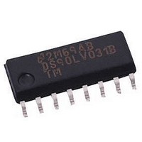
SP2526-2EN-L Exar Corporation, SP2526-2EN-L Datasheet

SP2526-2EN-L
Specifications of SP2526-2EN-L
Available stocks
Related parts for SP2526-2EN-L
SP2526-2EN-L Summary of contents
Page 1
... Maximum On-Resistance DESCRIPTION The SP2526 device is a dual +3.0V to +5.5V USB Supervisory Power Control Switch ideal for self-powered and bus-powered Universal Serial Bus (USB) applications. Each switch has low on-resistance (80mΩ typical) and can supply 500mA minimum. The fault currents are limited to 2 ...
Page 2
... C above+70 C)...............1000mW Unless otherwise noted, the following specifications apply for Date: 11/03/04 = +5.0V ° µ µ mΩ < Ω Ω µ Ω µ Ω µ Ω µ SP2526 +3.0V to +5.5V USB Power Control Switch < < © Copyright 2004 Sipex Corporation ...
Page 3
... Pin 4 — ENB — Enable Input for MOSFET Switch B. This input pin is active high for the SP2526-1 and active low for the SP2526-2. . Date: 11/03/04 SP2526 +3.0V to +5.5V USB Power Control Switch 1 8 OUTA ...
Page 4
... IN 4) Current Limiting Threshold: A current limiting threshold prevents damage to the de- vice and external load. 5) Thermal Shutdown: This mechanism pro- tects the SP2526 and signals a fault condition if the die temperature exceeds 135 O This function has hysteresis that pre- vents the MOSFET switches from turning on until the die temperature drops to 125 cal) ...
Page 5
... Figure 1. Internal Block Diagram for the SP2526 Date: 11/03/04 SP2526 +3.0V to +5.5V USB Power Control Switch © Copyright 2004 Sipex Corporation 5 ...
Page 6
... Figure 2. Test Circuit for the SP2526 100kΩ 100kΩ USB Controller Figure 3. Typical Application Circuit for the SP2526 Date: 11/03/04 SP2526 +3.0V to +5.5V USB Power Control Switch V IN 0.1µ SP2526 Ferrite Bead 8 OUTA 1 ENA 2 FLGA ...
Page 7
... The respective fault flag will pull low until the condition is removed. When a heavy load is connected to the SP2526 switch output, a large transient current may flow until the current limiting circuitry responds. The SP2526 will provide a low resistance switch (100mΩ ...
Page 8
... USB logic controller, elimi- nating the need for the RC filter. Soft Start Condition The soft start feature of the SP2526 is imple- mented by holding the output turn-on rise time to 1ms. When off, the device has high imped- ance MOSFET channels that slowly become low impedance as the device powers on ...
Page 9
... Table 1. USB Protocol Compliance of the SP2526 device Date: 11/03/04 SP2526 +3.0V to +5.5V USB Power Control Switch Controller V IN OVERCURRENT 0.1µF to 1.0µF 0.1µF Figure Filter for Overcurrent Faults USB V IN 10kΩ SP2526 ENA 1 8 OUTA 10kΩ FLGA 2 ...
Page 10
... Controller USB Cable V BUS USB Host 4.7µF GND Figure 6. Soft Start Circuit Configuration for a Single Channel USB-powered Application with the SP2526 USB Controller USB Cable V BUS USB Host 4.7µF GND Figure 7. Soft Start Circuit Configuration for SP2526 Applications with Large Load Capacitances Date: 11/03/04 SP2526 +3 ...
Page 11
... Figure 9. Output On-Resistance vs. Temperature Enable Threshold Voltage vs. Supply Voltage 2.3 2.1 1.9 1.7 1.5 1.3 1.1 0.9 2 100 Figure 11. Control Threshold vs. Supply Voltage SP2526 +3.0V to +5.5V USB Power Control Switch 11 Output On-Resistance vs. Temperature Vcc=5V - Temperature (°C) Enable Voltage Rising Enable Voltage Falling 3 3 ...
Page 12
... Figure 13. Off-state Supply Current vs. Supply Voltage 5.0 4.5 4.0 3.5 3.0 2.5 2.0 1.5 1.0 0.5 0.0 - 100 Figure 15. Off-state Supply Current vs. Temperature SP2526 +3.0V to +5.5V USB Power Control Switch 12 Offstate Supply Current vs. Supply Voltage 3.5 4 4.5 5 Supply Voltage (V) Offstate Supply Current vs. Temperature Vcc=5V Switches Disabled - ...
Page 13
... Enable Voltage Falling 1.7 1.5 -40 - Temperature (°C) Figure 16. Control Threshold vs. Temperature FLAG V OUT I OUT Figure 18. Current-Limit Response With a Ramped Load Date: 11/03/04 SP2526 +3.0V to +5.5V USB Power Control Switch = + unless otherwise noted. AMB Vcc= OUT FLAG I OUT 60 80 100 Figure 17. Input Voltage Response EN ...
Page 14
... OUT 200mA/ Div = Figure 21. Short Circuit Response (Enable into Short L Circuit) FLAG V OUT I OUT 1A/DIV Figure 23. Short Circuit Transient Response (Short Applied To Output) SP2526 +3.0V to +5.5V USB Power Control Switch 14 SP2526 Rev B 0.5A/DIV SP2526 Rev B 2A/DIV © Copyright 2004 Sipex Corporation ...
Page 15
... PERFORMANCE CHARACTERISTICS (continued +5.0V, single MOSFET switch section, and FLAG V OUT I OUT Figure 24. Short Circuit Response (Enable into Short Circuit) Date: 11/03/04 SP2526 +3.0V to +5.5V USB Power Control Switch = + unless otherwise noted. AMB SP2526 Rev 1Ω L 3.5 3 2.5 2 1.5 ...
Page 16
... DIMENSIONS (Inches) Minimum/Maximum (mm Ø Date: 11/03/04 SP2526 +3.0V to +5.5V USB Power Control Switch PACKAGE: PLASTIC SMALL OUTLINE (SOIC) (NARROW 45° L 8–PIN 14–PIN 0.053/0.069 0.053/0.069 (1.346/1.748) (1.346/1.748) 0.004/0.010 0.004/0.010 (0.102/0.249 (0.102/0.249) 0.014/0.019 0.013/0.020 (0.35/0.49) (0.330/0.508) 0.189/0.197 0.337/0.344 (4.80/5.00) (8.552/8.748) 0.150/0.157 0.150/0.157 (3 ...
Page 17
... SP2526 +3.0V to +5.5V USB Power Control Switch 17 DUAL–IN–LINE (NARROW) C Ø 0.300 BSC A (7.620 BSC) 18–PIN 20–PIN 22–PIN 0.115/0.195 0.115/0.195 (2.921/4.953) (2 ...
Page 18
... Date: 11/03/04 SP2526 +3.0V to +5.5V USB Power Control Switch Temperature Range = lead free. SP2526-2EN-L/TR 18 Package Types © Copyright 2004 Sipex Corporation ...


