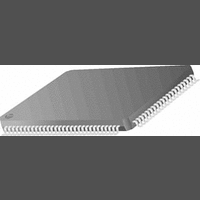
DS90CR484VJD National Semiconductor, DS90CR484VJD Datasheet - Page 4

DS90CR484VJD
Manufacturer Part Number
DS90CR484VJD
Description
IC SERDES 112MHZ 48BIT 5.38GBPS TQFP-100
Manufacturer
National Semiconductor
Datasheet
1.DS90CR483VJD.pdf
(22 pages)
Specifications of DS90CR484VJD
Serdes Function
Receiver
Data Rate
5.38Gbps
Ic Output Type
CMOS, TTL
No. Of Inputs
8
No. Of Outputs
48
Supply Voltage Range
3V To 3.6V
Driver Case Style
TQFP
No. Of Pins
100
Lead Free Status / RoHS Status
Contains lead / RoHS non-compliant
Available stocks
Company
Part Number
Manufacturer
Quantity
Price
Company:
Part Number:
DS90CR484VJD
Manufacturer:
NS
Quantity:
853
Part Number:
DS90CR484VJD
Manufacturer:
NS/国半
Quantity:
20 000
Company:
Part Number:
DS90CR484VJD/NOPB
Manufacturer:
NS
Quantity:
277
Company:
Part Number:
DS90CR484VJD/NOPB
Manufacturer:
Texas Instruments
Quantity:
10 000
Company:
Part Number:
DS90CR484VJDX/NOPB
Manufacturer:
Texas Instruments
Quantity:
10 000
www.national.com
LVDS DRIVER DC SPECIFICATIONS
|V
∆V
V
∆V
I
I
LVDS RECEIVER DC SPECIFICATIONS
V
V
I
TRANSMITTER SUPPLY CURRENT
ICCTW
ICCTZ
RECEIVER SUPPLY CURRENT
ICCRW
ICCRZ
TCIT
TCIP
TCIH
TCIL
TXIT
OS
OZ
IN
Symbol
Electrical Characteristics
OS
TH
TL
Over recommended operating supply and temperature ranges unless otherwise specified.
Recommended Transmitter Input Characteristics
Over recommended operating supply and temperature ranges unless otherwise specified.
OD
Symbol
OD
OS
|
TxCLK IN Transition Time (Figure 4)
TxCLK IN Period (Figure 5)
TxCLK in High Time (Figure 5)
TxCLK in Low Time (Figure 5)
TxIN Transition Time
Differential Output
Voltage
Change in V
between
Complimentary Output
States
Offset Voltage
Change in V
between
Complimentary Output
States
Output Short Circuit
Current
Output TRI-STATE
Current
Differential Input High
Threshold
Differential Input Low
Threshold
Input Current
Transmitter Supply
Current
Worst Case
Transmitter Supply
Current
Power Down
Receiver Supply
Current
Worst Case
Receiver Supply
Current
Power Down
Parameter
OD
OS
Parameter
R
V
PD = 0V, V
V
V
V
R
BAL = High,
Worst Case Pattern
(Figures 1, 2)
PD = Low
Driver Outputs in TRI-STATE during power down
Mode
C
Worst Case Pattern
(Figures 1, 3)
PD = Low
Receiver Outputs stay low during power down
mode.
OUT
CM
IN
IN
L
L
L
= 100Ω
= 100Ω, C
= 8 pF, BAL = High,
= +2.4V, V
= 0V, V
= +1.2V
(Continued)
= 0V, R
OUT
CC
L
L
CC
= 3.6V
= 100Ω
= 5 pF,
= 0V or V
= 3.6V
Conditions
4
CC
f = 33 MHz
f = 66 MHz
f = 112 MHz
f = 33 MHz
f = 66 MHz
f = 112 MHz
8.928
0.35T
0.35T
Min
1.0
1.5
0.5T
0.5T
Typ
2.0
1.125
−100
T
Min
250
−3.5
1.25
91.4
Typ
345
106
155
125
200
250
±
20
5
1
0.65T
0.65T
Max
30.3
3.0
6.0
1.375
+100
Max
±
±
±
450
140
160
210
150
210
280
100
35
35
−5
50
10
10
10
Units
Units
mV
mV
mV
mA
mV
mV
mA
mA
mA
mA
mA
mA
µA
µA
µA
µA
µA
ns
ns
ns
ns
ns
V


