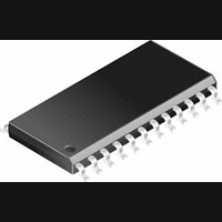
SI9961ACY Vishay, SI9961ACY Datasheet - Page 7

SI9961ACY
Manufacturer Part Number
SI9961ACY
Description
IC, MOTOR DRIVER VOICE COIL 1.8A SOIC-24
Manufacturer
Vishay
Type
Voice Coil Motor Driverr
Datasheet
1.SI9961ACY.pdf
(9 pages)
Specifications of SI9961ACY
Motor Type
Voice Coil
No. Of Outputs
2
Output Current
1.8A
Output Voltage
9.1V
Supply Voltage Range
4.5V To 5.5V
Driver Case Style
SOIC
No. Of Pins
24
Operating Supply Voltage
- 0.3 V to + 16 V
Supply Current
13 mA
Mounting Style
SMD/SMT
Package / Case
SO-24
Operating Temperature
0 C to + 70 C
Lead Free Status / RoHS Status
Contains lead / RoHS non-compliant
Available stocks
Company
Part Number
Manufacturer
Quantity
Price
Company:
Part Number:
SI9961ACY
Manufacturer:
SILI
Quantity:
5 510
Company:
Part Number:
SI9961ACY
Manufacturer:
LATTICE
Quantity:
5 510
Part Number:
SI9961ACY
Manufacturer:
SILICON LABS/芯科
Quantity:
20 000
Part Number:
SI9961ACY-T1
Manufacturer:
VISHAY/威世
Quantity:
20 000
If a unit step voltage is applied to the above transfer function
and the inverse Laplace transform is taken, the output result is:
Where
As we can see, if x = p (i.e. if the VCM pole and compensation
amplifier zero = the transconductance closed loop pole), then
Vo reduces to A. In other words, a step input results in a step
output without overshoot. If x < p then a step input results in an
increased rise time output and no overshoot. If x > p, a step
input results in a step output with an overshoot.
If this overshoot is large enough, there may be a
cross-conduction condition in the output FETs.
Let us look at the above equation at t = 0 and t >> 0, expressed
in terms of the open loop high frequency voltage gain, A.
In the example shown above, p = 10,000 and A = 9.8. This
means that there is some overshoot. At t = 0, the output voltage
is 9.8 V per volt of input. At some later time, it has dropped to
7.5 V per volt of input. An overshoot of 31 % is thus produced.
The
consideration, since it constitutes a potentially catastrophic
problem area. If we had decided to optimize for no overshoot,
A would equal 7.5, and hence the closed loop pole (A * B / Lv)
would be 10,000, which is a frequency of 1.592 kHz. This
would have resulted in a phase margin degradation of 13_ at
the 367-Hz frequency desired. This may or may not be
acceptable. One must weigh the servo bandwidth, phase
margin degradation, and maximum voltage at the VCM for
each individual case.
Document Number: 70014
S-40845—Rev. H, 03-May-04
V
V
V
O
O
O
+ A
+ A
+
maximum
p
t = time
B
L
p ) ( x * p ) x e
v
overshoot
x
At t = 0
At t uu 0
*x
voltage
t
requires
careful
Result:
In the example for the 2081-Hz roll-off case with 31%
overshoot and proper pole cancellation, the compensation
values are:
In the example for the 1592-Hz roll-off case with no overshoot
and proper pole cancellation, the compensation values are:
The linearity of the transconductance amplifier (around a
center value of 500 mA/volt) is shown in Figure 2. In this case,
the output current sense resistors (R
tolerance, 0.5 W . Any mismatch between R
contribute directly to mismatch between the positive and
negative “full-scale”. Including the external resistor mismatch,
the overall loop nonlinearity is approximately 1% maximum
over a "250-mV input voltage range.
R
C
R
C
−1
−2
−3
−4
−5
5
4
3
2
1
0
L
L
L
L
−300
FIGURE 2. Si9961A Transconductance
= 6.2 kW
= 0.016 mF
= 4.7 kW
= 0.022 mF
V
R
R
G
DD
SA
m
m
−200
= 52 W
= 500 mA/V
= 12 V
= R
SB
End Point Non-Linearity
−100
= 0.5 W ”5%
V
IN
in mV
0
Vishay Siliconix
100
SA
and R
200
Si9961A
SB
SA
www.vishay.com
) were "5%
300
and R
SB
7


