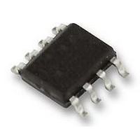
LM3404MA National Semiconductor, LM3404MA Datasheet - Page 11

LM3404MA
Manufacturer Part Number
LM3404MA
Description
DRIVER, LED, 1A, POWERWISE, SO-8, 3404
Manufacturer
National Semiconductor
Datasheet
1.LM3404MA.pdf
(28 pages)
Specifications of LM3404MA
Led Driver Application
Automotive, Industrial Lighting
No. Of Outputs
1
Output Current
1.2A
Output Voltage
40V
Input Voltage
6V To 42V
Dimming Control Type
PWM
Operating
RoHS Compliant
Topology
Buck
Available stocks
Company
Part Number
Manufacturer
Quantity
Price
Part Number:
LM3404MAX
Manufacturer:
NS/国半
Quantity:
20 000
Part Number:
LM3404MAX/NOPB
Manufacturer:
NS/国半
Quantity:
20 000
CCM operation, the converter maintains a constant switching
frequency that can be selected using the following equation:
AVERAGE LED CURRENT ACCURACY
The COT architecture regulates the valley of ΔV
portion of V
is also the average inductor current) the valley inductor cur-
rent is calculated using the following expression:
In this equation t
CS comparator, and is approximately 220 ns. The average
inductor/LED current is equal to I
ductor current ripple, Δi
Detailed information for the calculation of Δi
Design Considerations section.
MAXIMUM OUTPUT VOLTAGE
The 300 ns minimum off-time limits the maximum duty cycle
of the converter, D
age, V
The maximum number of LEDs, n
a single series string is governed by V
mum forward voltage of the LEDs used, V
expression:
At low switching frequency the maximum duty cycle and out-
put voltage are higher, allowing the LM3404/04HV to regulate
output voltages that are nearly equal to input voltage. The
following equation relates switching frequency to maximum
output voltage, and is also shown graphically in the Typical
Performance Characteristics section:
V
F
= forward voltage of each LED, n = number of LEDs in
O(MAX)
SNS
, determined by the following equations:
. To determine the average LED current (which
SNS
MAX
I
F
represents the propagation delay of the
= I
, and in turn the maximum output volt-
L
L
:
= I
series
L-MIN
L-MIN
+ Δi
MAX
L
, that can be placed in
plus one-half of the in-
/ 2
O(MAX)
F(MAX)
L
is given in the
and the maxi-
SNS
, using the
, the AC
11
MINIMUM OUTPUT VOLTAGE
The minimum recommended on-time for the LM3404/04HV is
300 ns. This lower limit for t
cycle and output voltage that can be regulated based on input
voltage and switching frequency. The relationship is deter-
mined by the following equation, shown on the same graphs
as maximum output voltage in the Typical Performance Char-
acteristics section:
HIGH VOLTAGE BIAS REGULATOR
The LM3404/04HV contains an internal linear regulator with
a 7V output, connected between the VIN and the VCC pins.
The VCC pin should be bypassed to the GND pin with a 0.1
µF ceramic capacitor connected as close as possible to the
pins of the IC. VCC tracks VIN until VIN reaches 8.8V (typical)
and then regulates at 7V as VIN increases. Operation begins
when VCC crosses 5.25V.
INTERNAL MOSFET AND DRIVER
The LM3404/04HV features an internal power MOSFET as
well as a floating driver connected from the SW pin to the
BOOT pin. Both rise time and fall time are 20 ns each (typical)
and the approximate gate charge is 6 nC. The high-side rail
for the driver circuitry uses a bootstrap circuit consisting of an
internal high-voltage diode and an external 10 nF capacitor,
C
MOSFET is off. When the MOSFET turns on, the internal
diode reverse biases. This creates a floating supply equal to
the V
when its source voltage is equal to V
FAST SHUTDOWN FOR PWM DIMMING
The DIM pin of the LM3404/04HV is a TTL compatible input
for low frequency PWM dimming of the LED. A logic low (be-
low 0.8V) at DIM will disable the internal MOSFET and shut
off the current flow to the LED array. While the DIM pin is in
a logic low state the support circuitry (driver, bandgap, VCC)
remains active in order to minimize the time needed to turn
the LED array back on when the DIM pin sees a logic high
(above 2.2V). A 75 µA (typical) pull-up current ensures that
the LM3404/04HV is on when DIM pin is open circuited, elim-
inating the need for a pull-up resistor. Dimming frequency,
f
time and fall time and the delay from activation of the DIM pin
to the response of the internal power MOSFET. In general,
f
steady state switching frequency in order to prevent aliasing.
PEAK CURRENT LIMIT
The current limit comparator of the LM3404/04HV will engage
whenever the power MOSFET current (equal to the inductor
current while the MOSFET is on) exceeds 1.5A (typical). The
power MOSFET is disabled for a cool-down time that is ap-
proximately 75x the steady-state on-time. At the conclusion
of this cool-down time the system re-starts. If the current limit
condition persists the cycle of cool-down time and restarting
will continue, creating a low-power hiccup mode, minimizing
thermal stress on the LM3404/04HV and the external circuit
components.
OVER-VOLTAGE/OVER-CURRENT COMPARATOR
The CS pin includes an output over-voltage/over-current
comparator that will disable the power MOSFET whenever
DIM
DIM
B
. V
, and duty cycle, D
should be at least one order of magnitude lower than the
CC
CC
charges C
voltage minus the diode drop to drive the MOSFET
B
through the internal diode while the power
DIM
, are limited by the LED current rise
ON
determines the minimum duty
IN
.
www.national.com


