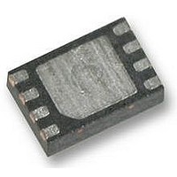
AS1506BTDT100 austriamicrosystems, AS1506BTDT100 Datasheet - Page 10

AS1506BTDT100
Manufacturer Part Number
AS1506BTDT100
Description
IC, DIGITAL POT 100KOHM, 256, SGL TDFN-8
Manufacturer
austriamicrosystems
Datasheet
1.AS1506BTDT10.pdf
(17 pages)
Specifications of AS1506BTDT100
End To End Resistance
100kohm
Track Taper
Linear
No. Of Steps
256
Supply Voltage Range
2.7V To 5.5V
Control Interface
Serial, SPI
No. Of Pots
Single
Memory Type
EEPROM
Lead Free Status / RoHS Status
Lead free / RoHS Compliant
AS1506
Data Sheet - D e t a i l e d D e s c r i p t i o n
EEPROM (Non-Volatile Register)
There is an internal EEPROM register implemented to retain the wiper position after power down. During an ongoing
write cycle of the non-volatile register (t
Data retention defines the ability of an EEPROM to retain data over time. The qualification has been done according to
JEDEC Retention Lifetime Specification (A117). The EEPROM is cycled to the specified endurance limit before the
data retention test is done. Based on activation energy of 0.6eV the data retention time derates over temperature as
shown in
For the non-volatile register 1M endurance cycles and a data retention of 150 years are typical at 85 ºC. The non-vola-
tile register is factory trimmed to mid-scale.
Power-Up
The AS1506 contains an integrated power-up circuit. At power up, the data are transferred from the non-volatile mem-
ory to the wiper register. The wiper register moves to the stored position. This data transfer takes 5µs after the supply
has reached the POR trigger level.
Programming the Device
Write commands
Copy and Read commands
or 16 clock cycles. At 16 clock cycle commands the 8 data bits (D7:D0) are insignificant.
Table 6. Command/Data Word Format
Commands
Write Wiper Register
This is a 16-bit command
MSB bit of the command, the second byte represents the data written to the wiper register (starting with the MSB).
Data 0000 0000 the wiper moves the closest position to LOW, with data 1111 1111 the wiper moves to the closest posi-
tion to HIGH.
Note: At power-up the wiper position stored in the non-volatile memory are automatically loaded into the wiper regis-
Write to Non-Volatile Register
This is a 16-bit command
MSB bit of the command, the second byte represents the data written to the non-volatile memory. The wiper position is
not changed by this command, since the wiper register is not affected.
There is a write non-volatile register time defined in the timing specification, which is required for storing the data in the
non-volatile register. During this time the device must not be powered down, otherwise the data stored in the non-vola-
tile register is corrupted.
www.austriamicrosystems.com
Write to Non-Volatile Register
Copy Wiper Register to Non-
Copy Non-Volatile Register
Read Non-Volatile Register
Write Wiper Register
Read Wiper Register
to Wiper Register
ter, the wiper moves to the related position.
Volatile Register
Figure 19 on page
Command
(see Table 6)
(see Figure 22 on page
(see Figure 22 on page
(see Table 6)
8.
require 16 clock cycles
C7
1
0
0
0
0
0
0
C6
BUSY
2
0
0
0
0
0
1
can use 8 clock cycles to clock in the command
C5
time) the system must not be powered down.
3
0
0
1
1
1
1
C4
12). The first byte represents the command word starting with the
12). The first byte represents the command word starting with the
0
1
4
0
1
0
0
Revision 1.01
(see Figure 22 on page 12)
C3
5
0
0
0
0
1
1
C2
6
0
0
0
0
0
0
C1
7
0
0
0
0
0
0
C0
8
0
0
0
0
0
0
D7
D7
D7
9
-
-
-
-
D6
D6
D6
10
to clock in the command and data.
-
-
-
-
D5
D5
D5
11
-
-
-
-
(see Figure 21 on page 11)
D4
D4
D4
12
-
-
-
-
D3
D3
D3
13
-
-
-
-
D2
D2
D2
14
-
-
-
-
D1
D1
D1
15
-
-
-
-
10 - 17
D0
D0
D0
16
-
-
-
-


