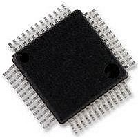
CS42432-DMZ Cirrus Logic Inc, CS42432-DMZ Datasheet - Page 27

CS42432-DMZ
Manufacturer Part Number
CS42432-DMZ
Description
IC, AUDIO CODEC, 24BIT, 200KHZ, MQFP-52
Manufacturer
Cirrus Logic Inc
Datasheet
1.CS42432-CMZ.pdf
(58 pages)
Specifications of CS42432-DMZ
Audio Codec Type
Stereo
No. Of Adcs
4
No. Of Dacs
6
No. Of Input Channels
4
No. Of Output Channels
6
Adc / Dac Resolution
24bit
Sampling Rate
200kSPS
Ic Interface Type
I2C
Lead Free Status / RoHS Status
Lead free / RoHS Compliant
Available stocks
Company
Part Number
Manufacturer
Quantity
Price
Company:
Part Number:
CS42432-DMZ
Manufacturer:
Cirrus Logic Inc
Quantity:
10 000
Company:
Part Number:
CS42432-DMZR
Manufacturer:
Cirrus Logic Inc
Quantity:
10 000
DS673F2
5.2
5.2.1
5.2.2
Status Interrupt
Analog Inputs
5.2.1.1
AIN Volume Control and ADC Overflow status are not accessible in Hardware Mode.
5.2.1.2
Line-Level Inputs
AINx+ and AINx- are the line-level differential analog inputs internally biased to VQ, approximately VA/2.
Figure 9 on page 27
ended signals on all inputs, AIN1-AIN4. See
filters.
For single-ended operation on ADC1-ADC2 (AIN1 to AIN4), the ADCx_SINGLE bit in the register
Control & DAC De-Emphasis (Address 05h)” on page 42
page 48
The gain/attenuation of the signal can be adjusted for each AINx independently through the
Control (Address 11h-14h)” on page
puts above positive full scale or below negative full scale, the ADC will output 7FFFFFH or 800000H, re-
spectively, and cause the ADC Overflow bit in the register
to be set to a ‘1’.
High-Pass Filter and DC Offset Calibration
The high-pass filter continuously subtracts a measure of the DC offset from the output of the decimation
filter. If the high-pass filter is disabled during normal operation, the current value of the DC offset for the
corresponding channel is frozen and this DC offset will continue to be subtracted from the conversion re-
sult. This feature makes it possible to perform a system DC offset calibration by:
Function
for required external components).
Hardware Mode
Software Mode
3.9 V
1.1 V
3.9 V
1.1 V
Table 2. Hardware Configurable Settings (Continued)
2.5 V
2.5 V
shows the full-scale analog input levels. The CS42432 also accommodates single-
(AINx+) - (AINx-) = 5.6 V
Full-Scale Differential Input Level =
Hardware Mode Feature Summary
Figure 9. Full-Scale Input
Default Configuration
45. The ADC output data is in 2’s complement binary format. For in-
PP
= 1.98 V
N/A
“ADC Input Filter” on page 48
RMS
“Status (Address 19h) (Read Only)” on page 46
must be set appropriately (see
AINx-
AINx+
Hardware Control
VA
-
for the recommended input
5.0 V
-
“AINX Volume
CS42432
Figure 20 on
Note
“ADC
27


