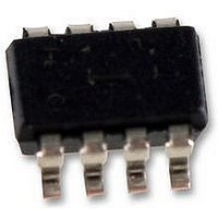
HT1381-8SOPLF HOLTEK, HT1381-8SOPLF Datasheet - Page 4

HT1381-8SOPLF
Manufacturer Part Number
HT1381-8SOPLF
Description
IC, TIMEKEEPER, SERIAL, SMD, SOP8
Manufacturer
HOLTEK
Datasheet
1.HT1381-8SOPLF.pdf
(10 pages)
Specifications of HT1381-8SOPLF
Clock Format
HH
Clock Ic Type
Timekeeper
Supply Voltage Range
2V To 5.5V
Digital Ic Case Style
SOP
No. Of Pins
8
Operating Temperature Range
0°C To +70°C
Date Format
DD
Lead Free Status / RoHS Status
Lead free / RoHS Compliant
Functional Description
The HT1380/HT1381 mainly contains the fol-
lowing internal elements: a data shift register
array to store the clock/calendar data, com-
mand control logic, oscillator circuit and read
timer clock. The clock is contained in eight
read/write registers as shown below. Data con-
tained in the clock register is in binary coded
decimal format.
Two modes are available for transferring the
data between the microprocessor and the
Command byte
For each data transfer, a Command Byte is initiated to specify which register is accessed. This is to
determine whether a read, write, or test cycle is operated and whether a single byte or burst mode
transfer is to occur. Refer to the table shown below and follow the steps to write the data to the chip.
First give a Command Byte of HT1380/HT1381, and then write a data in the register.
This table illustrates the correlation between Command Byte and their bits:
Note: ²x² stands for don¢t care
Select Read or Write Cycle
Specify the Register to be Accessed
Clock Halt Flag
For IC Test Only
Select Single Byte or Burst Mode
Symbol
t
t
t
t
t
t
r
f
CC
CCH
CWH
CDZ
Function Description
Clock Rise and Fall Time
Reset to Clock Setup
Clock to Reset Hold
Reset Inactive Time
Reset to I/O High Impedance
Parameter
V
2V
5V
2V
5V
2V
5V
2V
5V
2V
5V
DD
Test Conditions
C7
C
1
1
4
Conditions
HT1380/HT1381. One is in single-byte mode
and the other is in multiple-byte mode.
The HT1380/HT1381 also contains two addi-
tional bits, the clock halt bit (CH) and the write
protect bit (WP). These bits control the opera-
tion of the oscillator and so data can be written
to the register array. These two bits should first
be specified in order to read from and write to
the register array properly.
C6
0
0
¾
¾
¾
¾
¾
¾
¾
¾
¾
¾
C5
0
1
Command Byte
C4
1
1
Min.
240
60
¾
¾
¾
¾
4
1
4
1
C3
A2
x
1
HT1380/HT1381
Max.
C2
A1
2000
500
280
x
1
¾
¾
¾
¾
¾
¾
70
September 18, 2000
C1
A0
x
1
Unit
ns
us
ns
us
ns
R/W
C0
1
x


